
2D Toolpaths #
The 2D toolpaths machine your vectors at set depths: Profile cuts along them, Pocket clears the area inside them, Drilling makes holes at them, V-Carve carves them with a V-bit and Quick Engrave traces them at a fixed depth. They cover most sign making, cut-out and joinery work.
Each one has a button in the Toolpath Operations section of the Toolpaths tab and an entry in the Toolpaths menu. Select the vectors first, open the form, set the options and click Calculate (see Making a toolpath). The options the forms share, such as Start depth, Cut depth, the Tool and its Tool Settings, are described in the Toolpaths chapter.
Profile #
A profile toolpath cuts along the selected vectors: outside them to cut parts out, inside them to cut holes, or on the line for grooves. It can leave tabs to hold the parts, ramp into the cut instead of plunging, and lead in and out from the side.
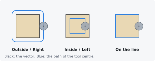
Profile works with closed and open vectors. Closed vectors inside other closed vectors count as holes in the shape: cutting a letter O on the outside cuts around its outline and inside its hole, so the ring is what is left.
Carvio cuts each vector to its full depth, pass after pass, before moving to the next one, and takes the vectors in nearest-first order starting from the home position. Each pass of a closed vector starts near the vector's first point. Between passes of a closed vector the tool goes straight down at the same spot; on an open vector it lifts and starts each pass from the beginning again.
Tip: When cutting parts out of a sheet, cut a little deeper than the material (see Cut depth) and use tabs so the parts do not come loose and get caught by the tool on the last pass.
Machine vectors #
Chooses where the tool runs compared with the vectors: Outside / Right, Inside / Left or On the line. Outside keeps the shape you drew as the part; Inside makes the hole the shape you drew.
See Outside / Right, Inside / Left and On the line. For open vectors, right and left are seen looking along the direction the vector was drawn; if a cut lands on the wrong side, pick the other side option or reverse the vector.
The Climb and Conventional options below choose the cut direction; see Climb and Conventional.
Allowance offset #
Moves the toolpath further from the vector (a positive value) or closer into it (a negative value), on top of the tool's radius. A positive allowance leaves a thin skin of material on the part for a finishing pass.
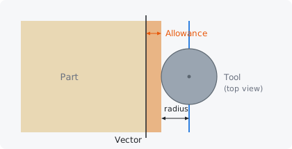
A common way to get a clean edge is two profiles with the same tool: a roughing profile with an allowance of 0.2 to 0.5 mm (0.01 to 0.02 inch) taken to full depth, then a finishing profile at 0 that takes one full-depth pass (set its pass depth to the full depth in its Tool Settings). A small negative allowance makes a part slightly smaller or a hole slightly bigger, for example for a looser fit.
The allowance has no effect On the line: the tool then simply follows the vector.
Reverse direction #
Runs every pass the other way round from what Climb or Conventional would give. On an outside or inside profile this swaps climb for conventional milling; it is mostly useful for cuts On the line and for open vectors, where it decides which end the cut starts from and which way it travels.
Tabs #
Tabs are short bridges of material the profile leaves at the bottom of the cut, so a part cut out of the sheet stays attached to it until you cut it free. They are only made on closed vectors.
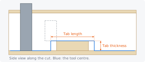
Over each tab, the tool centre lifts to the top of the tab and comes down again after it. Only the passes that go deeper than the top of the tabs are affected; the passes above them run all the way round. Afterwards, cut the tabs with a chisel, a flush-trim saw or a utility knife and sand the stubs flush.
Add tabs to toolpath #
Leaves tabs on every closed vector of the profile. With it ticked, the tab options appear below it.
Tabs are not needed for cuts that do not go through the material, or when the parts are held by a vacuum table or screws.
Tabs per vector #
The number of tabs on each closed vector. Carvio spaces them evenly along each toolpath loop, starting half a spacing from where the loop begins.
Use at least 2 for small parts and 3 to 6 for larger ones; one every 150 to 250 mm (6 to 10 inches) of outline is a good guide. A vector too short for its tabs (shorter than the tab length times the number of tabs) gets none. To put tabs exactly where you want them, for example on straight edges where they are easy to trim, place them by hand.
Tab length #
How long each tab is, measured along the toolpath: the distance over which the tool centre stays up on the tab.
The bridge of material left at full thickness is about one tool diameter shorter than this, because the tool cuts half its width into each end of the tab. With a 6 mm bit, a tab length of 10 to 15 mm leaves a bridge of 4 to 9 mm.
Tab thickness #
How tall each tab is, measured up from the bottom of the cut (the cut depth). A thicker tab holds better but is more work to cut away.
For 18 mm (3/4 inch) wood, tabs 3 to 5 mm thick are usual; thin sheet needs thinner tabs, 1 to 2 mm. Remember that the tab top is the cut depth minus the thickness: if you cut 0.5 mm into the spoilboard, half a millimetre of the tab is below the material.
3D tabs (ramped) #
Ramps the tool up onto each tab and down again at 45 degrees, instead of lifting straight up. The tool never stops moving forward, which is kinder to the tool and leaves no dwell marks.
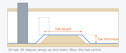
The ramps are added on both sides of the tab length, each as long as the tab is thick, and the material left under them makes the tab wider at its base. 3D tabs are on by default; untick it to get square tabs, which are a little quicker to trim.
Placing tabs by hand #
Set tab positions lets you put the tabs where you want them on the selected vectors: the 2D view shows a handle for each tab, which you drag along its vector. Automatic tabs goes back to evenly spaced tabs.
The first time, the handles start at the automatic positions (the number in Tabs per vector on each selected closed vector). Then:
- drag an orange handle to slide the tab along its vector;
- click a selected vector to add a tab there;
- right-click a handle to remove that tab.
Click Done when you are finished, then Calculate. The form says how many tabs were placed by hand; Edit tab positions brings the handles back to change them. Each tab is kept as a position along its own vector, so it follows the vector when you move or resize it.
Ramps and leads #
A plain profile plunges straight down into the material at the start of every pass. A ramp or a lead lets the tool enter more gently.
Ramp plunge #
Lets the tool go down into the material while it moves along the cut, instead of plunging straight down. Linear descends in one slope along the path; Zigzag goes forward and back along the start of the path. None plunges straight in.
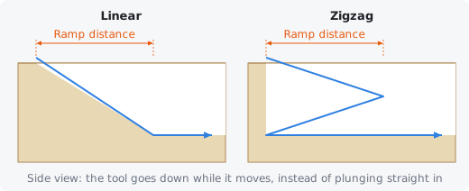
Ramping spreads the load of entering the material over a length of cut, which helps bits that do not plunge well (many straight-flute and compression bits), stops burn marks at the entry point and is easier on small tools.
- Linear, on a closed vector, starts half a millimetre above the pass, slopes down along the path over the ramp distance, carries on round at full depth and, at the end of the loop, cuts the ramped stretch again at full depth so no slope is left in the cut.
- Zigzag moves forward over the ramp distance while going down half the way, comes back to the start going down the rest, then cuts the pass.
On open vectors the ramp always zigzags, and each pass ramps down from the top. Ramps are cut at the feed rate, not the plunge rate. When a lead in/out is set, the lead is used instead of the ramp.
Ramp distance #
How far along the path the ramp runs while the tool goes down. A longer ramp is a gentler slope.
The slope is the depth of the pass over the ramp distance. A ramp distance of three to five times the pass depth gives a shallow slope that suits most bits; 10 mm (about 3/8 inch) is the default. The ramp is never longer than the vector itself.
Lead in/out #
Starts and ends each pass with a short approach from the waste side of the cut, so the tool does not plunge or stop right on the finished edge. Straight comes in at an angle; Arc sweeps in along a quarter circle that meets the cut tangentially. None starts right on the cut.
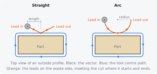
With a lead, the tool plunges at the start of the lead, beside the cut, moves in along the lead to the cut, goes round, and leaves along the lead out at the end. It then lifts to the safe Z and does the same for the next pass. An arc lead gives the cleanest edge where the cut starts and ends; it is a good choice for finished parts.
The lead is on the side away from the material: outside an outside profile and inside an inside profile, so make sure there is room for it there (a lead inside a small hole may hit the far side).
Lead length/radius #
The size of the lead: the length of a straight lead, or the radius of an arc lead.
A straight lead starts this far back along the cut and half this far out to the side. About the tool diameter, 3 to 6 mm (1/8 to 1/4 inch), is usually enough.
Pocket #
A pocket toolpath clears all the material inside the selected closed vectors down to the cut depth, leaving a flat floor. Use it for recesses, inlays, lettering backgrounds and clearing large areas.
Pocketing only uses closed vectors (open ones are skipped; see Open vectors in the selection). A closed vector inside another one is an island: it is left standing in the middle of the pocket. So a pocket of a letter O clears the ring and leaves the centre.
The tool centre stays one tool radius (plus the pocket allowance) inside the outline, so the walls of the pocket land on the vectors. Each depth level is cleared completely before the next one. Where the tool can travel from one ring or line to the next inside the pocket, it moves across at depth; otherwise it lifts to the safe Z and plunges again. Pockets plunge straight down, at the plunge rate, so use a tool that can plunge (a centre-cutting end mill) and keep the plunge rate modest.
To clear a big pocket faster, or one whose corners need a small tool, add a bigger clearance tool in the Clear row.
Offset #
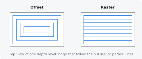
Clears the pocket with rings that follow its outline, each one a stepover inside the last. Offset pockets follow the shape closely and leave a clean wall, and suit most shapes, especially round and irregular ones.
The rings are cut from the middle of the pocket outwards, with the outermost ring (the wall) last or first as set by Profile pass. Every ring is cut in the chosen Climb or Conventional direction.
Raster #
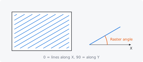
Clears the pocket with parallel back-and-forth lines, a stepover apart, at the Raster angle. Raster pockets suit long, straight-sided shapes and can leave a nicer floor, because every line runs the same way across the grain.
Because the lines go back and forth, half of them climb mill and half conventional mill; the cut direction applies to the profile pass round the wall. The ends of the lines leave small scallops along the wall, which the profile pass cleans up.
Raster angle #
The direction of the raster lines, in degrees from the X axis: 0 runs them along X, 90 along Y. Choose the angle that runs along the longest side of the pocket, or along the grain of the wood for the smoothest floor.
Profile pass #
Decides when the tool runs once round the wall of the pocket. Last cuts it after the clearing, which leaves the cleanest wall; First cuts it before the clearing; None leaves it out.
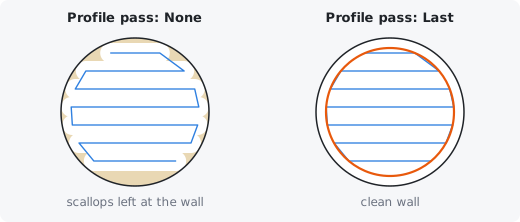
- With Offset, the outermost ring is the wall itself. Last cuts it at the end of each depth level (and None does the same, since the rings work outwards to it anyway). First cuts it before the inner rings, which outlines the shape early at each level.
- With Raster, Last and First both add a pass round the wall after the raster lines of each level. None leaves the scalloped edge the line ends make, which is fine when a profile or another toolpath cleans the wall later.
Pocket allowance #
Leaves this much material on the walls of the pocket (the floor still goes to the cut depth). Use it to rough out a pocket quickly and then clean the walls with a separate finishing pass.
0.2 to 0.5 mm (0.01 to 0.02 inch) is a typical roughing allowance. Clean up the wall afterwards with an inside Profile at the same cut depth and no allowance.
Stepover override #
A stepover for this pocket only, in place of the tool's stepover. Leave it at 0 to use the stepover from the Tool Settings.
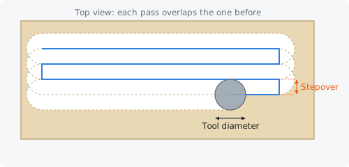
It does the same as editing the stepover in the Tool Settings; the override wins when both are set. A clearance tool always uses its own stepover.
Drilling #
A drilling toolpath plunges the tool straight down at each selected vector to make holes: one hole per vector, at the centre of a closed vector (the middle of its bounding box) or at the first point of an open one. Use it with drill bits, or with an end mill for holes the size of the bit.
Draw a small circle where each hole goes, select them all and drill them in one toolpath; the holes are visited in nearest-first order from the home position, lifting to the safe Z between them. Each hole goes from the Start depth to the Cut depth at the plunge rate. The pass depth is not used: set Peck depth to drill in steps.
Tip: The cut depth is the depth of the drill's point. A pointed drill (118 degrees) only reaches its full diameter about 0.3 × the diameter above its point, so add that to the depth for a hole that must be full size at the bottom. For holes bigger than the bit, use an inside Profile or a Pocket instead.
Peck depth #
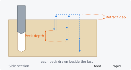
Drills the hole in steps of this depth, lifting out between them to clear the chips. 0 drills the whole hole in one plunge.
After each peck the tool rapids up out of the hole to the retract gap above the top of the hole, then rapids back down to just above (0.5 mm) the bottom it reached and drills the next peck. Peck when a hole is deeper than about three times its diameter, or in materials that pack the flutes, such as hardwood, plastics and aluminium; a peck depth of about one diameter is a good start. If the hole is no deeper than one peck, it is drilled in one go.
Retract gap #
How far above the top of the hole (the start depth) the tool lifts between pecks to clear the chips. It is only used with a Peck depth.
1 mm (about 0.04 inch), the default, lifts the bit just clear of the hole so the chips can fly out without wasting time; raise it if chips pile up around the hole.
V-Carve / Engraving #
A V-carve toolpath carves the selected closed vectors with a V-bit, the tool following the centre line of each shape and going deeper where the shape is wider, so the sloping sides of the bit touch both edges. It gives the crisp, chiselled look of hand-carved lettering.
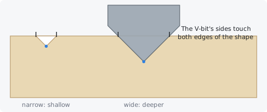
V-carving only uses closed vectors, such as text and outlines; a closed vector inside another (the centre of an O) is left uncarved. Narrow strokes are carved shallow and wide ones deeper, so the depth follows the design: there is no cut depth to set. The deepest the bit can go is where it reaches its full diameter; a shape wider than that is carved to that depth and its middle cleared flat, as with a Flat depth.
A V-carve deeper than the tool's pass depth is cut in stages, each going down to an even share of the full depth, so a big bit is not buried in one go. Parts of a shape narrower than an engraving bit's flat tip are not cut.
Tip: Smaller angles carve deeper for the same width: a 60 degree bit goes about 1.7 times as deep as a 90 degree one. Use 90 degrees for large sign lettering, 60 degrees for general carving and 30 degrees for fine detail and small text.
Start depth #
Lowers the surface the carve starts from by this much: the whole carve is moved down. Leave it at 0 to carve from the top of the material.
Use it to carve into a flat area that was already pocketed to a known depth. To carve into a curved or uneven machined surface, use Project onto the machined surface instead.
V-Bit #
The V-bit (or engraving bit) that carves the shapes. Its included angle and tip decide how deep each width is carved, and its diameter decides how deep it can go.
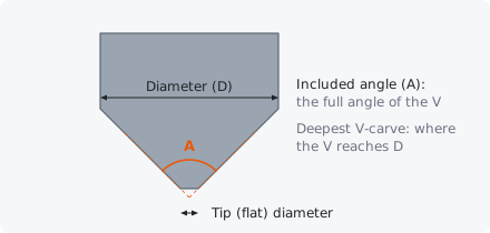
Pick a tool of type V-Bit or Engraving from the Tool Database; the form warns when the tool chosen is not one. Check the bit's included angle and diameter carefully: a wrong angle carves every letter to the wrong depth.
Flat depth #
Limits the carve to this depth: where a shape is wide enough to go deeper, the bit carves its walls down to the flat depth and the area between them is cleared flat at that depth. Tick Flat depth to set the depth and offer a clearance tool.
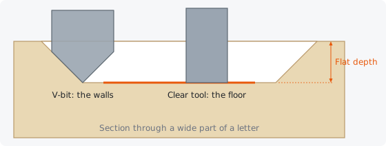
Use a flat depth for large lettering and shapes that would otherwise be carved far too deep, and for a carved look with a flat bottom. With a flat depth, the V-bit:
- carves the narrow parts as usual,
- runs round the edge of each flat area at the flat depth, which forms the sloping walls,
- clears the flat floor with offset passes, after the Clear tool has done most of it if one is chosen.
Without a clearance tool, the V-bit clears the whole floor itself, which is slow, and a pointed bit leaves fine ridges between its passes. Set a clearance tool for any sizeable flat area.
Clear #
An end mill that clears the flat floors of a V-carve with a flat depth, so the V-bit only has to cut the walls and the corners. Leave it at None to let the V-bit clear the floors on its own.
The clearance tool gets its own toolpath, named with [Clear] on the end and placed before the V-carve in the list. It clears the floors from the start depth down to the flat depth in passes of its own pass depth, with its own stepover, using the Clear strategy. Afterwards the V-bit cleans up whatever the end mill could not reach. A 3 mm or 6 mm (1/8 or 1/4 inch) end mill suits most lettering. See Clear for more about clearance tools.
Clear strategy #
How the clearance tool clears the flat floors: Offset rings that follow the shape, or Raster lines along X.
Offset suits letters and curved shapes; raster can be quicker on large, blocky areas. Both work like the Pocket strategies of the same name, climb milling, with a pass round the edge at the end.
Quick Engrave #
Quick Engrave traces the selected vectors with the tool centre right on the line, at one fixed depth, in a single pass. Use it for engraved lines, signatures, single-line fonts, centre-line text, marking out and scoring.
It works with open and closed vectors, keeps arcs as arcs, and visits the vectors in nearest-first order from the home position, lifting to the safe Z between them. The width of the engraved line is the width of the tool at that depth: for a V-bit or engraving bit, the deeper you go the wider the line.
Unlike a profile, there is no offset, no pass depth (the whole depth is cut in one go) and no tabs; for deeper grooves use a Profile On the line.
Depth #
How deep the tool engraves, below the material surface (or below the machined surface with Project onto the machined surface). It is cut in one pass, so keep it shallow.
For a 90 degree V-bit, the line is twice as wide as it is deep (plus the tip's width): a 0.5 mm deep line is about 1 mm wide. Typical engraving depths are 0.2 to 1 mm (0.01 to 0.04 inch). Projection is handy here: it keeps an engraved line at an even depth on a surface that is not quite flat.
Tool for engraving #
Any tool can engrave, but a V-bit or an engraving bit gives fine lines that are sharp at the corners. A small ball nose gives a round-bottomed groove, and a small end mill a groove the width of the bit.
Pick it in the Tool row. The Tool Settings' feed and plunge rates are used; keep them moderate for small engraving bits, which break easily.