
Tools and Materials #
Every toolpath is cut with a tool from the Tool Database. The database describes each cutter's shape, so Carvio can work out where its edge goes, and holds its cutting values (pass depth, stepover, speeds and feeds), which can differ for each material in the Material Database.
Set up your own bits once, with their real sizes and the values that work on your machine, and every new toolpath starts from them. This chapter covers the Tool Database, the Form Tool Designer for shaped cutters, and the Material Database.
The Tool Database #
The Tool Database is the library of your cutting tools: end mills, ball noses, V-bits, drills, form tools and lasers, each with its geometry and cutting values. Open it with Toolpaths > Tool Database..., the Tool Database button on the Toolpaths tab, or Select... next to a toolpath form's Tool row.
The list of tools is on the left; the selected tool's settings are on the right. Changes are made straight to the tool and saved when you close the dialog (the line at the bottom says which folder the library is kept in). The library belongs to your computer, not to a project, so the same tools are there in every job.
Opened from a toolpath form, the dialog is for picking: double-click a tool, or select it and click Select, to use it in the form.
New, Copy and Delete #
New adds a 6 mm end mill called "New Tool" at the end of the list, ready to be edited. Copy makes a copy of the selected tool just below it, the quickest way to add a tool like one you have. Delete removes the selected tool (the last tool cannot be deleted).
Toolpaths you have already calculated keep their own copy of their tool, so deleting or changing a tool does not change them until they are recalculated. A recalculated toolpath uses its own tool again, wherever it now is in the list (see Tool).
Import... and Export... #
Export... saves the whole Tool Database as a .carviotools file: every tool with its
geometry, its cutting values and its values per material. Use it to back up your tools, to
move them to another computer or to share them.
Import... adds the tools of a .carviotools file (or a .carvtool file from an earlier Carvio, or Carvio's own tools.json) to the
database. A tool you already have with the same values is skipped; a tool with the name of a
different tool you have comes in as "name (imported)", so nothing of yours is overwritten.
The line at the bottom of the dialog says how many tools came in.
Select #
Uses the selected tool in the toolpath form the database was opened from, and closes the dialog. It only appears when the database was opened from a form's Select... button.
Name #
The tool's name, as shown in the tool lists, the Toolpath List, the setup sheets and the G-code comments. Include what tells your bits apart: the type, size and angle, for example "V-Bit 60deg 12.7mm" or "Compression 6mm".
Tool type #
The kind of cutter. It sets the shape of the tool's tip, which the simulation uses to cut the stock and the V-carve, 3D and form toolpaths use to work out depths, and it decides which geometry fields the dialog shows.
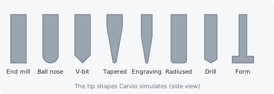
The kinds are described in Kinds of tool. Choose the kind that matches the bit's tip: a wrong type gives toolpaths and previews that do not match what the bit really cuts.
Kinds of tool #
Carvio knows nine kinds of tool. Each has a different tip shape and its own geometry fields.
End Mill #
A flat-bottomed cutter: the general purpose bit for profiles, pockets and drilling holes of its own size. Geometry: Diameter, Flute length and Number of flutes.
Up-cut bits clear chips well but can fray the top edge; down-cut bits leave a clean top edge; compression bits do both on sheet goods. Carvio does not need to know which, but put it in the name.
Ball Nose #
A cutter with a round tip, its radius half the diameter. Use it for 3D finishing, fluting and round-bottomed grooves. Geometry: Diameter and the flute fields.
V-Bit #
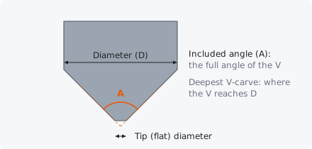
A cone-shaped cutter for V-carving, chamfers and engraving. Geometry: Diameter (its widest cutting diameter), Included angle and, for a bit with a flat end, Tip (flat) diameter.
Tapered Ball Nose #
A cone with a small ball on the end, strong and fine at once: the favourite for detailed 3D carving. Geometry: Diameter, Ball diameter and Taper angle.
Engraving #
A fine, pointed engraving bit, often with a tiny flat tip. It has the same fields as a V-bit and can V-carve, which suits small text. Geometry: Diameter, Included angle and Tip (flat) diameter.
Radiused End Mill #
An end mill with rounded corners (a bull nose). It leaves a small fillet at the bottom of walls and is a good 3D roughing tool. Geometry: Diameter and Corner radius.
Drill #
A twist drill with a pointed tip, for the Drilling toolpath. Geometry: Diameter, Included angle (the point angle, usually 118 degrees) and Tip (flat) diameter (0 for a pointed drill).
Form Tool #
A shaped cutter: T-slot and keyhole cutters, dovetails, round-overs, beading and moulding bits. Its shape is a half-section you draw in the Form Tool Designer; without one it cuts like a flat end mill of its diameter. Form tools are run along edges with the Edge Form toolpath.
Laser #
A laser module, for the laser toolpaths. Its "diameter" is the Beam width (the kerf), and its values are a line interval, power and speed instead of spindle speed and feeds.
Geometry #
The Geometry fields describe the cutter's size and shape. Measure your bits (or read the maker's data) and enter them accurately: the diameter decides where every profile and pocket wall lands. The geometry is entered in millimetres (1/4 inch is 6.35 mm, 1/8 inch 3.175 mm).
Diameter (D) #
The cutting diameter of the tool. Profiles and pockets offset the tool centre by half of it, so an error here makes every part and hole the wrong size by the same amount.
For a V-bit, engraving bit or tapered ball nose, it is the widest diameter of the cutting part (usually the shank end of the cone): V-carving can go no deeper than where the bit reaches it. For a form tool, changing the diameter scales the whole profile.
Tip: Measure a bit by cutting a test slot and measuring it: worn or cheap bits are often a little under their nominal size.
Beam width (kerf) #
For a laser: the width of the line the beam burns, typically 0.08 to 0.2 mm. The laser cut toolpath offsets by half of it, as profiles do with a tool's radius.
Included angle (A) #
The full angle of the V, from one side of the cone to the other: 90 degrees for a 90 degree V-bit, 60 for a 60 degree one. For a drill it is the point angle, usually 118 degrees.
V-carving uses this angle to work out how deep to go for each width, so it must be right. Some makers quote the angle from the axis (half the included angle); double it before entering it.
Tip (flat) diameter #
The diameter of the flat at the end of a V-bit, engraving bit or drill, 0 for a sharp point. Many engraving bits have a tip of 0.1 to 0.5 mm.
A flat tip carves a little shallower for each width than a sharp V of the same angle, and parts of a V-carve narrower than the tip are not cut.
Ball diameter #
For a tapered ball nose: the diameter of the ball at its tip. A "1 mm tapered ball nose" has a ball diameter of 1 mm (a ball radius of 0.5 mm).
Taper angle (incl.) #
For a tapered ball nose: the included angle of the taper, from one side to the other. Makers often quote the angle per side; double it. A "5.4 degree" taper is 10.8 degrees included.
Corner radius #
For a radiused end mill: the radius of the rounded corners at the end of the bit. It cannot be more than half the diameter (at half the diameter the tool is a ball nose).
Flute length #
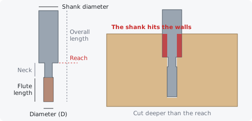
How long the cutting part of the bit is, from the tip to the end of the flutes. Carvio draws the tool with it (in the Tool Database, the tool sheet and the 3D views) and checks the toolpaths against it: a pass deeper than the flutes is warned about, and with the shank it sets how deep the tool can reach next to the material (see Shank clearance). It is not used for lasers, and for a form tool it follows the profile's height.
Shank diameter #
The diameter of the shank, the plain part the collet holds. 0 means the same as the cutting diameter (for a form tool: the same as its neck). Small bits usually sit on a larger shank: a 1.5 mm end mill on a 3.175 mm (1/8 inch) shank, say.
When the shank is as wide as the cut or wider, it cannot follow the tool down into a narrow cut: the tool reaches only its flute length (plus a neck) below the shank. Toolpaths that cut deeper next to standing material are flagged, and the Preview shows where the shank meets the material in red (see Shank clearance). A shank narrower than the cut, as on a large V-bit or surfacing bit, always clears.
Neck length #
A relieved neck between the flutes and the shank: a reduced-diameter part that clears the walls of the cut, found on long-reach bits. It adds to how deep the tool reaches below its shank. 0 when the shank starts right above the flutes. For a form tool, the neck is the profile's top radius carried up before the shank.
Overall length #
The length of the whole bit, from the tip to the end of the shank. It is used to draw the tool; 0 when not known (the tool is then drawn with a likely length).
The drawing under these fields shows the tool from the side, tip on the left: the flutes shaded, its diameter, flute length and shank, and, when the shank is at least as wide as the cut, a red line where the shank starts (the tool's reach).
Number of flutes #
How many cutting edges the bit has. It is for your reference and the tool sheet: use it to work out a feed rate from a chip load (see Feed rate).
Design profile... #
For a form tool: opens the Form Tool Designer to draw the cutter's shape. The line above the button sums up the current profile: its number of points, diameter, height and whether it is an undercut cutter.
Cutting values #
The Cutting Parameters and Feeds and Speeds fields are the values a toolpath starts with when you pick the tool: Pass depth, Stepover, Spindle speed, Feed rate and Plunge rate. A toolpath can still change them for itself in its Tool Settings.
The values you see are the tool's defaults, or its own values for one material, as chosen in For material above them. The best values depend on your machine, the bit and the material, so start from the bit maker's advice and adjust after a test cut.
Cutting values per material #
A tool can hold different cutting values for each material: slower in hardwood, faster in MDF and foam. For material chooses which values the fields below show and edit: Tool defaults, or one of the materials of the Material Database.
- Tool defaults are used for any material the tool has no values of its own for, and when the job has no material set.
- Choose a material to give the tool its own values for it. If it has none yet, the fields show the defaults (greyed); click Set values for... to start from them and change them.
- Remove deletes the tool's values for that material, so the defaults apply to it again.
When a toolpath form picks a tool, it takes the tool's values for the material chosen in Job Setup. A laser's focal length is the same for every material.
Materials... #
Opens the Material Database, to add or rename the materials a tool can have values for.
Lengths (diameters, pass depth, stepover...) are shown in the app's distance unit and the feed, plunge and laser speeds in its speed unit, both set in Edit > Preferences....
Line interval #
For a laser: the distance between the lines of a fill or picture, the laser's stepover. About the beam width (0.08 to 0.15 mm) gives a solid fill; a bigger interval is quicker but shows lines.
Power #
For a laser: the power the beam burns at, as a percentage of its maximum. The post processor turns it into the controller's S value.
Focal length #
For a laser on a machine with a Z axis: how far the module sits above its focus when Z zero is set on the material surface. Leave it at 0 when you set Z zero with the beam already focused on the material.
Speed #
For a laser: how fast the head moves while it burns, in the app's speed unit. Slower burns darker and deeper.
Tool number #
The tool's number (0 to 999), the T number in the G-code's tool changes. It is also shown on the setup and tool sheets, in tool change messages, and in the file names when the toolpaths are saved one file per tool.
If your machine has a tool changer or a tool table, give each tool the number of its pocket or its entry there. On a machine with manual tool changes, a different number for each bit you own makes the tool change messages clear.
Notes #
Anything you want to remember about the tool: where you bought it, the collet it needs, the results of a test cut.
Choosing a tool #
Pick the tool in each toolpath form's Tool row. As a rough guide for a CNC router:
| Job | Tool | Toolpath |
|---|---|---|
| Cutting parts out of sheet | 6 mm (1/4 inch) end mill; compression for plywood and laminate | Profile, Outside |
| Pockets and recesses | 6 mm end mill, plus a 3 mm one for tight corners | |
| Sign lettering | 60 or 90 degree V-bit | V-Carve |
| Small text, fine lines | 30 degree V-bit or engraving bit | V-Carve or Quick Engrave |
| Holes | drill, or an end mill of the hole's size | Drilling |
| 3D roughing | 6 mm end mill or radiused end mill | 3D Roughing |
| 3D finishing | ball nose or tapered ball nose | 3D Finishing |
| Mouldings, slots, undercuts | form tool | Edge Form |
A bigger tool is stiffer and clears material faster; a smaller tool reaches into tighter corners. An inside corner can never be sharper than the tool's radius, so choose the tool for the smallest inside corner of the design (or clear with a big tool and finish with a small one, see Clear).
The starter tools #
Carvio comes with a starter library in metric sizes: end mills of 6, 3.175 and 1.5 mm, ball noses of the same sizes, V-bits of 90, 60 and 30 degrees, a 1 mm tapered ball nose, a 0.2 mm 20 degree engraving bit, a 3 mm drill, a 0.1 mm laser and a set of form tools (T-slot, keyhole, dovetail, undercut cove, half-round edge, round-over, a classical moulding and an undercut ball).
Their cutting values are reasonable starting points for wood, not tuned for any one machine. Edit them to match your bits, or copy one and change it, before you rely on them.
Form Tool Designer #
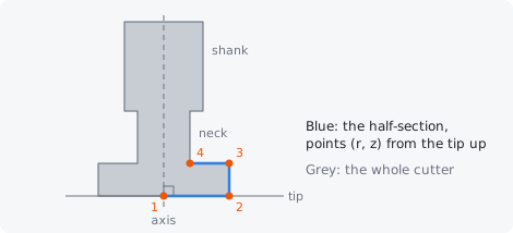
The Form Tool Designer draws the shape of a form tool: its half-section, the outline of the cutter from the tip up, as a radius at each height. Carvio cuts, simulates and previews the tool with this shape.
Open it from the Tool Database: set Tool type to Form Tool and click Design profile.... To make a new form tool from a shape you have drawn, select the open vector in the 2D view, right-click it and choose Form Tool from Vector...: Carvio adds a new form tool to the library with that section and opens it in the designer.
The left side holds the section and its settings; the right side shows the cutter revolved in 3D. Click OK to put the shape into the tool (and save the library), or Cancel to leave the tool as it was.
The section #
The section is drawn against the tool's axis (the vertical line) and its tip (the horizontal line), the corner in the middle at the bottom; the grey outline around it shows the whole cutter, mirrored, with its neck and shank.
Edit it with the mouse:
- drag a point to move it; hold
Shiftto keep the drag horizontal, vertical or at 45 degrees, and holdCtrlto switch the grid snap off (or on) while dragging; - click a segment to add a point there (and drag it at once);
- double-click empty space to add a point at the end;
- right-click a point, or select it and press
Delete, to remove it.
Snap to 0.5 mm puts points on a half-millimetre grid; points dropped very close to the axis land on it. New section starts again with a plain flat cutter of the current diameter. After every edit the lowest point becomes the tip, so heights are always measured from it.
A section that comes back in towards the axis above its widest point makes an undercut cutter (a T-slot, keyhole, dovetail or undercut cove). The designer marks it, because such a tool cannot plunge into the material: it has to enter from the side at its cutting height, which the Edge Form toolpath does. A tool without an undercut can plunge and can be used in any toolpath.
Profile from the selected vector #
Replaces the section with the vector selected in the 2D view. Draw the section as an open vector, with its ends on the axis side and its lowest point as the tip; it can face left or right.
Draw it full size, as it would look cut through the middle of the bit, from the tip up. The axis is taken as the vertical line through the end nearer to it.
Form Tool from Vector #
Makes a new form tool from the open vector selected in the 2D view and opens it in the Form Tool Designer. Find it on the vector's right-click menu.
The vector is read as the cutter's half-section, the same way as Profile from the selected vector. The new tool is named "Form tool" and a number and is added to the end of the Tool Database's list; rename it there and check its feeds and speeds before you use it.
Presets #
Ready-made sections for common cutters. Choose the Cutter, set its sizes and click Use this preset to replace the section with it.
- T-slot cutter and Keyhole cutter: a blade of the Diameter and Blade thickness on a neck of the Neck diameter.
- Dovetail: the Diameter at the tip, a Cutting height and a Side angle (14 degrees is common).
- Undercut cove (barrel): a rounded barrel of the Diameter and Cutting height on a neck.
- Half-round edge (bullnose): two full-width flanges with a half-round groove of the Groove diameter between them.
- Round-over: a cutter that rounds an edge to the Rounding radius; it stays full width above the rounding, so it has no undercut.
Size #
Diameter (scales) scales the whole section so its widest point has this diameter. Neck length is how far the section's top radius carries on up before the shank; Shank diameter is the shank above it (0 uses the neck's diameter). Flutes sets the number of cutting edges drawn in the preview.
The neck and shank are solid in the simulation too, so a cutter run too deep shows the gouge its neck would make.
Points (r, z) #
Every point of the section as numbers: its radius (distance from the axis) and its height above the tip. Type exact values from the maker's drawing here. The cross removes a point (a section needs at least two), and Add a point adds one 2 mm above the last.
The cutter preview #
The right side shows the cutter revolved into a solid, with helical flutes on its cutting part. Drag it to turn it; Reset view turns it back. Untick Show the flutes to see the plain revolved shape.
The line under the preview says whether the cutter undercuts. At the bottom of the dialog, the cutter's diameter, height and number of points are shown.
Material Database #
The Material Database lists the materials your jobs are cut from: softwood, hardwood, plywood, MDF, acrylic, HDPE, aluminium, brass, foam, stone and solid surface to start with. Each has a name, an appearance for the 3D view and simulation, and notes.
Open it with Toolpaths > Material Database... or the Materials... button in the Tool Database. A job's material is chosen in Job Setup; tools then use their cutting values for that material, and the stock is painted with its appearance. The materials are saved when you close the dialog.
The editor shows how many tools have their own cutting values for the selected material; the others use their defaults.
New and Delete #
New adds a material called "New material"; give it a name and an appearance. Delete removes the selected material, and with it every tool's cutting values for it (the last material cannot be deleted).
Name #
The material's name, shown in Job Setup and the Tool Database. Tools keep their values for a material by its name; renaming a material here keeps them with it, and keeps the current job on it too.
Appearance #
How the stock of this material looks in the 3D view and the toolpath preview: woods (pine, oak, maple, walnut, cherry, mahogany, plywood), MDF, HDPE, acrylics in several colours, stones (granite, marble, slate), metals (aluminium, brass, copper), foam and solid surface. The swatch below shows its colour.
A job can choose a different appearance for itself in Job Setup, for example to show a cherry board while using the hardwood cutting values.
Notes #
A description of the material, such as which woods or grades it covers ("Pine, spruce, cedar"). It is for your reference.