
Toolpaths #
A toolpath is the route the tool takes through the material: where it plunges, how deep it goes, which way it travels and how fast. You make toolpaths from your vectors (and from the 3D model) on the Toolpaths tab, check them in the preview, then save them as G-code for your machine.
This chapter explains how toolpaths work in general and the options that most toolpath forms share: the depths, the tool and its cutting values, the cut direction and the side of the vector. The individual 2D toolpaths are described in 2D Toolpaths; the tools themselves live in the Tool Database.
The Toolpaths tab #
The Toolpaths tab is where you create, edit and organise the toolpaths of the job. It has three sections: Material Setup, Toolpath Operations and the Toolpath List.
When a toolpath form is open (Profile, Pocket and so on), it takes the place of these sections on the tab. Click Close at the bottom of the form to get the sections back.
Material Setup #
The Material Setup section shows the material thickness and where Z zero is, and holds the two heights every toolpath uses: the safe Z and the home position.
The thickness and Z zero come from Job Setup; click Job Setup... to change them.
Safe Z #
Safe Z is the height the tool rapids at between cuts, measured from the job's Z zero. Make it high enough to clear clamps, screws and hold-downs; 5 mm (about 0.2 inch) above the material is a common starting point.
Warning: Safe Z is measured from Z zero, not from the top of the material. If your Z zero is the machine bed (see Z zero position), a safe Z of 5 mm is inside 18 mm material. Set it to the thickness plus your clearance.
A toolpath takes the safe Z when it is calculated. If you change it later, recalculate the toolpaths (Recalculate all in the Toolpath List) so their moves use the new height.
Home X Y Z #
The home position is where the program starts and ends, in the job's coordinates. Each toolpath also starts with the cut nearest to home, then moves on to the nearest next one.
The default is X 0, Y 0, Z 20 mm. Home Z is measured from Z zero, like Safe Z, so keep it above the material and anything clamped to it. See Home position and safe Z for how the posts use it.
Toolpath Operations #
The Toolpath Operations section has a button for each kind of toolpath. Select the vectors to machine, then click the button to open its form.
The same operations are on the Toolpaths menu. The bottom row of the section has buttons for the toolpath preview, Save Toolpaths, the setup and tool sheets and the Tool Database.
Preview, Save Toolpaths and Setup Sheets #
The Preview button opens the toolpath preview, which simulates the toolpaths cutting the material so you can check the result before you machine it. See Previewing toolpaths.
Save Toolpaths button #
Opens the Save Toolpaths form, which writes the toolpaths as G-code for your machine through a post processor. See Saving G-code.
Setup Sheets button #
Opens the setup and tool sheets: printable pages (saved as PDF) with the job's material, Z zero, tools and toolpaths for whoever runs the machine. See Setup and Tool Sheets.
Making a toolpath #
To make a toolpath, select the vectors, open the operation's form, set its options and click Calculate. Carvio works the toolpath out in the background and adds it to the Toolpath List.
- Select the vectors in the 2D view. A form uses the vectors that are selected when you click Calculate; the line above the buttons says how many are selected.
- Open the form from the Toolpath Operations section or the Toolpaths menu.
- Set the depths, pick the tool and check its Tool Settings.
- Click Calculate. A bar shows the progress while it works; the window stays usable. The status bar reports how long it took and the estimated machining time.
You can click Calculate again with other vectors selected (or other settings) to make another toolpath with the same form. Click Close when you are done.
Tip: Some operations make two toolpaths at once: a Pocket or V-Carve with a clearance tool adds a separate toolpath for the bigger tool, named after the main one with [Clear] on the end.
Name #
The name of the toolpath as it appears in the Toolpath List, the preview, the setup sheets and the comments of the G-code. A new form suggests the operation's name and a number, for example "Pocket 3"; type over it to give it a name that says what it does, such as "Cut out sign".
Open vectors in the selection #
Pocket and V-Carve (and the other operations that clear an area) only machine closed vectors. If the selection holds open vectors, the form warns how many will be skipped and offers a button to close them.
The Close open vector button joins each open vector's ends with a straight line. Vectors with only two nodes (a single line) cannot be closed, and neither can text. If the ends of a shape are only nearly touching, joining them properly (see Join) usually gives a better result than a straight closing line. See Open and closed vectors for more.
Profile, Drilling and Quick Engrave use open vectors as well as closed ones.
Editing and recalculating #
A toolpath remembers the vectors and settings it was made from, so you can change it later. Double-click it in the Toolpath List (or select it and click Edit) to open its form with its settings and its vectors selected again.
Change what you need and click Recalculate: the toolpath is replaced in place, keeping its place in the list. If you select other vectors before clicking Recalculate, the toolpath is remade from those.
When you move, resize or edit the vectors a toolpath was made from, the toolpath is marked out of date in the list (with a red warning sign). It is not changed until you recalculate it: use Recalc for one, or Recalculate out of date for all of them.
The Toolpath List #
The Toolpath List shows the toolpaths of the job in the order they will be cut. Each row has a checkbox, the toolpath's name and its tool; click a row to select it, double-click it to edit it.
On a job with several sheets, the list shows the toolpaths of the sheet you are working on; on a double-sided job, those of the side you are working on. Under the list, the total machining time of the toolpaths is shown.
When a toolpath is selected, the list shows its tool, its estimated time, the range of Z it cuts between and its number of moves, and the buttons below.
A row with a red warning sign and "shank hits" or "shank rubs" is a toolpath whose tool reaches deeper than its flutes next to standing material; select it to read why (see Shank clearance).
Tools the Tool Database lacks #
A project keeps a copy of every toolpath's tool, so it opens, previews and writes G-code on any computer. When it uses tools your Tool Database does not have (by name, kind and diameter), usually because it was made on another computer, a note at the top of the Toolpath List names them. Add to Tool Database adds them, with their geometry and cutting values. Until then the toolpaths keep using the project's copies, and editing or recalculating one adds its tool to the database first, so it is never recalculated with another tool.
Visibility #
The checkbox in front of a toolpath shows or hides it in the 2D and 3D views. Ticked toolpaths are also the ones Preview Visible simulates and Visible saves (see Saving G-code).
Untick the toolpaths you are not working on to keep the views clear.
Show in 2D #
Draws the toolpaths over the vectors in the 2D view (the same as Toolpaths in 2D view in the View menu). The 3D view has its own switch there, Toolpaths in 3D view.
Edit #
Opens the selected toolpath's form with its settings, and selects the vectors it was made from. Change the settings and click Recalculate.
Recalc #
Recalculates the selected toolpath from its own vectors and settings, without opening the form. Use it after changing the vectors, or after changing the tool's values in the Tool Database.
Delete #
Removes the selected toolpath from the job.
Duplicate #
Makes a copy of the selected toolpath right below it, named "... copy". Edit the copy to try another tool or depth without losing the original.
Move up and Move down #
Moves the selected toolpath one place up or down the list. The list order is the cutting order: the preview, the setup sheets and the G-code follow it.
Cut in an order that keeps the part held: engrave and pocket first, drill next, and cut the parts out last. Toolpaths that follow the machined surface depend on the toolpaths above them, so moving one can change them.
Recalculate out of date and Recalculate all #
Recalculate out of date remakes every toolpath whose vectors changed since it was made. Recalculate all remakes every toolpath of the job, which is handy after changing the safe Z, the home position or a tool's values.
Both run in the background; the bar under the list shows the progress.
Depths #
Every depth in a toolpath form is measured down from the top of the material, whatever you chose as Z zero, so a cut depth of 6 mm always means 6 mm into the material.
Start depth #
Start depth is how far below the material surface the first pass begins. Leave it at 0 for a cut that starts at the top of the material; set it when the top part has already been removed, for example to cut deeper inside an earlier pocket.
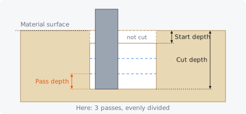
Carvio cuts the depth between the start depth and the cut depth in evenly divided passes, so nothing is wasted cutting air above the start depth. For a cut that should follow a carved or pocketed surface instead of a flat level, see Project onto the machined surface.
Cut depth #
Cut depth is the final depth of the cut below the material surface: the depth the tip of the tool reaches on its last pass.
To cut right through, set the cut depth a little more than the material thickness, typically 0.2 to 0.5 mm (0.01 to 0.02 inch) deeper, so the tool just scores the spoilboard. With a pointed tool (a V-bit or drill), remember that the full width is only reached some way above the tip.
The line under the depths tells you how many passes the cut takes and how deep each one is. The number of passes is the depth to cut (cut depth minus start depth) divided by the tool's pass depth, rounded up, and the passes are made equal. For example, 18.5 mm with a 6 mm pass depth takes 4 passes of 4.625 mm.
Shank clearance #
A tool can only reach as deep as its flute length (plus a relieved neck) below its shank. When the shank is as wide as the cut or wider, a cut deeper than that meets the walls with the shank: a shank as wide as the cutter rubs and burns them, a wider one (a 1.5 mm cutter on a 3.175 mm shank) hits them and can break the bit.
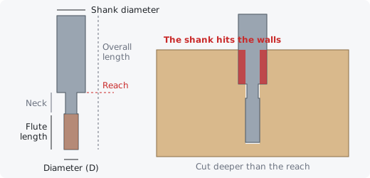
Carvio checks for it in three places:
- The toolpath form warns as soon as the cut depth is more than the tool's reach, or the pass depth more than its flute length.
- Once calculated, the toolpath is checked against the material as the toolpaths before it (and itself) leave it. Material cleared earlier, by a pocket with a larger tool say, is room for the shank, so a deep cut there is fine. A toolpath whose shank still meets standing material gets a red warning sign in the Toolpath List and on the setup sheet; select it to see how much too deep it goes.
- The Preview cuts with the shank too, and paints where it meets the material red.
To fix it: clear the material around the cut first with a larger tool, cut less deep, or use a tool with longer flutes or a relieved neck.
Project onto the machined surface #
Makes the toolpath follow the surface left by the toolpaths above it in the list, instead of the flat top of the material. Its depths are then measured from that machined surface, so an engraving or V-carve can run along a carved model or across the floor of an earlier pocket.
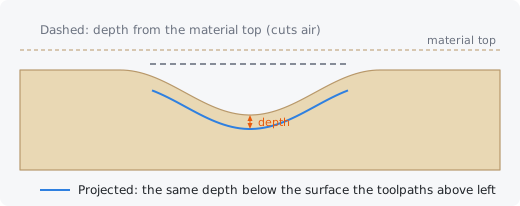
Carvio simulates the toolpaths above this one (those of the same sheet and side that are switched on) to find the surface, calculates the toolpath as usual, then lowers every cutting move by how far the surface lies below the material top at that point. Long moves and arcs are split into short steps so they follow the surface between their ends; rapid moves stay at the safe Z. Where nothing has been machined yet, the toolpath stays at the material top.
A projected toolpath is recalculated by itself when a toolpath above it changes. Because it depends on the order of the list, put it after the toolpaths that shape the surface it follows.
Tip: The surface is followed under the centre of the tool. On steep slopes the side of a wide tool can dig in or ride high, so projection works best with small tools and gentle surfaces, which is exactly the case for engraving and V-carving onto a relief.
To skip the parts of a toolpath that would cut air over an earlier pocket, without changing its depths, use Rest machining instead; see Rest machining or projection?.
Rest machining #
Cuts only the material that is still there: the cutting moves that would only cut air are left out of the toolpath. That means passes above the top of the material, passes that run off its edge, and passes through material the toolpaths above it in the list have already removed, such as a finishing pass over the floor of a pocket an earlier toolpath cleared, or a second profile's upper passes where a first one already went through. The tool rapids over the gap at the safe Z and plunges back in where the next cut meets material. It is on for every new toolpath, and toolpaths made before this option existed get it when they are recalculated.
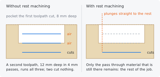
Carvio simulates the toolpaths above this one (those of the same sheet and side that are switched on, in list order) to find the stock they leave, in the same way as Project onto the machined surface, then checks each cutting move against it. A pass counts as cutting when the tool touches material anywhere along it: under the tool's centre, or around the tool out to its radius (a V-bit or ball nose sits higher at its sides, and that is allowed for). A pass that cuts for part of its length is kept whole. Like a projected toolpath, a rest machined one is recalculated by itself when a toolpath above it changes, and is marked out of date when the list order changes.
This is what stops a Moulding whose profile is taller than the material from sweeping the air above the top, and a 3D roughing from slicing above the material when the model's top sits below it. Switch it off to keep every pass, for example to trace a toolpath at the surface height on purpose or to re-cut a pocket floor for a cleaner finish (a toolpath that would lose all its cuts keeps them anyway).
Rest machining or projection? #
Both options look at the stock the toolpaths above leave, but they do different things with it, and they can be on together.
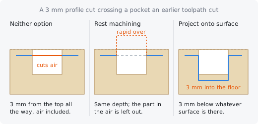
- Rest machining changes where the toolpath cuts, never how deep. The depths are measured from the material top as usual; the moves that find no material are left out. A profile that crosses an earlier pocket deeper than itself skips the part over the pocket. Use it to avoid cutting air: the default for every toolpath.
- Project onto the machined surface changes how deep the toolpath cuts, never where. Every move is lowered by the depth of the surface under it, so the depths are measured from the machined surface and the cut follows it: the same profile crossing that pocket dips down and cuts into its floor. Use it to engrave or V-carve onto a carved model or a pocket floor.
With both on, the toolpath is first projected, then checked for air against the same stock: a projected toolpath cuts everywhere it goes, so rest machining then only removes what lies above the material top or beyond its edge.
Lasers have no Rest machining option: they burn at their focus, so there are no passes in the air to leave out.
The tool #
Each toolpath form has a row to choose the tool and a Tool Settings section with the cutting values the toolpath will use. The tool itself is defined in the Tool Database.
Tool #
The Tool row picks the cutter for the toolpath from the tools in the Tool Database. Choose one from the list, or click Select... to open the database, where you can also add or change tools; double-click a tool there (or click Select) to use it.
When you pick another tool, the Tool Settings below change to that tool's values for the job's material. The toolpath keeps its own copy of the tool, so later changes in the Tool Database only reach it when you recalculate it.
When you recalculate a toolpath, it uses the same tool from the Tool Database, found by the tool itself (not by its place in the list), so adding, copying or reordering tools doesn't change it. A tool in the database only counts as the same when it is the same kind of tool with the same diameter. If the database no longer has it (it was deleted, or the project was made on another computer), the toolpath's own copy of the tool is added to the database and used (see Tools the Tool Database lacks).
Select... #
Opens the Tool Database to choose the tool for this row. Double-click a tool there, or select it and click Select, to put it in the row.
In the database you can also add a tool you are missing or correct a tool's values before you pick it.
Clear #
The Clear row picks an optional second, bigger tool to clear the bulk of an area quickly before the main tool. Leave it at None to do all the work with the main tool.
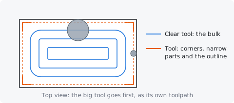
It is offered by the Pocket form and by the V-Carve form when Flat depth is ticked. The clearance tool gets its own toolpath (named with [Clear] on the end), placed before the main one in the list, and uses its own pass depth and stepover from the Tool Database for the job's material. The main tool then only cuts what the big tool could not reach: corners, narrow parts and the finished outline.
Use it with a fine tool that would take a long time to clear a large area: for example a 6 mm end mill to clear a pocket whose corners need a 3 mm one, or an end mill to clear the flat floor of a large V-carved letter. The line under the row shows the clearance tool's values; to change them, edit the tool in the Tool Database.
Tool Settings #
The Tool Settings section shows the cutting values the toolpath will use: pass depth, stepover, spindle speed, feed rate and plunge rate. They come from the chosen tool's values for the job's material in the Tool Database.
You can change any of them for this toolpath only: the tool in the database is not touched. The section then says Changed for this toolpath only, and Reset to defaults puts the tool's own values back. When the section is folded, a line sums the values up, with "(custom)" when they were changed.
Which values a tool starts with depends on the material chosen in Job Setup: a tool can hold its own values for each material (see Cutting values per material).
Pass depth #
Pass depth is the most the tool cuts down in one pass. A deeper cut is split into several passes of equal depth, each no deeper than this.
As a starting point for wood on a hobby router: about half the tool diameter for an end mill in hardwood, up to the full diameter in softwood and MDF with a 6 mm (1/4 inch) bit, and less for small bits (0.5 mm passes for a 1.5 mm bit). A smaller pass depth is gentler on the tool and the machine but takes longer.
V-Carve uses the pass depth too: a carve deeper than one pass depth is cut in stages. Quick Engrave and Drilling ignore it (drilling has its own Peck depth).
Stepover #
Stepover is how far the tool moves sideways between neighbouring passes when it clears an area, as a distance or as a percentage of the tool diameter. Each pass overlaps the one before by the diameter minus the stepover.
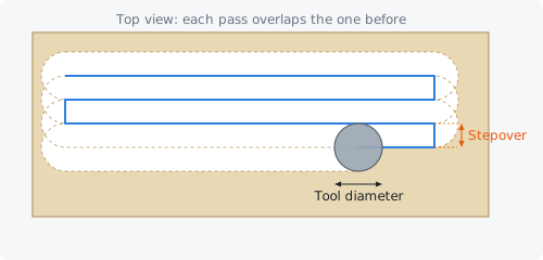
The two fields are linked: type a distance or a percentage and the other follows. For clearing pockets with an end mill, 40 to 50% is a good default; more than 50% risks leaving thin ridges. For finishing with a ball nose, 8 to 15% gives a smooth surface.
Pockets use the stepover between their offset rings or raster lines (unless the Pocket form's Stepover override is set), and V-Carve uses it to clear flat areas.
Spindle speed #
The spindle speed, in revolutions per minute, written into the G-code for the toolpath. Router spindles typically run from 12,000 to 24,000 rpm; 16,000 to 18,000 rpm is a common setting for wood.
If your spindle's speed is set by hand (a dial on a trim router), set this to match what you dial in, so the setup sheet tells you the right number. Together with the feed rate it decides how big a chip each cutting edge takes (see Feed rate).
Feed rate #
The feed rate is how fast the tool moves sideways through the material while it cuts, in the app's speed unit (Speed in Preferences: mm/min, mm/sec, inch/min or inch/sec).
A useful rule is: feed rate = spindle speed × number of flutes × chip load. For a 6 mm two-flute end mill in wood at 18,000 rpm and a chip load of 0.05 mm, that is 18,000 × 2 × 0.05 = 1,800 mm/min. Too slow a feed rubs and burns the wood and dulls the tool; too fast overloads it. Ramps and ramped tabs are cut at the feed rate too.
Plunge rate #
The plunge rate is how fast the tool moves straight down into the material, in the app's speed unit. Plunging is harder on a tool than cutting sideways, so it is usually a third to a half of the feed rate.
Every move that only goes down (the start of a pass, a drill peck) uses the plunge rate. To avoid plunging straight in on profiles, use a ramp.
Reset to defaults #
Puts the tool's own values for the job's material back into the Tool Settings, undoing changes made for this toolpath only.
Cut direction #
On profiles and pockets you choose whether the tool climb mills or conventional mills. The difference is which way the tool travels compared with the way it spins.
Climb #
In climb milling each cutting edge bites into the material at its thickest and leaves it at nothing, as if the tool were rolling along the cut. On most CNC routers this gives the cleaner edge and less heat, and it is the default.
With the spindle turning clockwise seen from above (M3, as on almost every router), a climb cut keeps the material on its right: it runs clockwise round the outside of a part and anticlockwise round a hole or a pocket's wall.
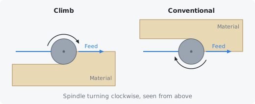
Climb milling pulls the tool along the cut, which a rigid machine handles well. On a light or flexible machine, or in material that tears out (some plywoods, end grain), try conventional instead, or use climb for the roughing passes and conventional for a light final pass.
Conventional #
In conventional milling each cutting edge starts at nothing and leaves at its thickest: the tool travels against its spin. It pushes the tool away from the cut, which is easier on a light or flexible machine. It runs the other way round from climb: anticlockwise round the outside of a part, clockwise round a hole or a pocket's wall.
Conventional milling can leave a rougher edge and rub more, because each edge slides a little before it starts to cut. Use it when climb milling chatters, pulls the tool into the work or splinters the edge.
Which side of the vector #
A profile can run outside a closed vector, inside it, or right on it. Carvio offsets the tool centre by the tool's radius so that the edge of the cut lands on the vector.
Outside / Right #
Cuts outside the vector: the tool centre runs one tool radius outside it, so the shape you drew is what remains. Use it to cut out parts. For an open vector, the tool runs on the right of the vector, looking along the direction it was drawn.
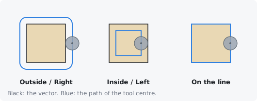
Inside / Left #
Cuts inside the vector: the tool centre runs one tool radius inside it, so the hole matches the shape you drew. Use it for holes, slots and openings. For an open vector, the tool runs on the left of the vector, looking along the direction it was drawn.
On the line #
The tool centre runs right on the vector, so the cut is centred on it and as wide as the tool. Use it for grooves, score lines and decorative lines where the width of the bit is the width you want.
Allowances and offsets do not apply on the line: the tool simply follows the vector.