
3D Modeling #
The Modeling tab builds a 3D relief: a surface that the 3D Roughing and 3D Finishing toolpaths carve into the material. You make the relief out of components: shapes raised from vectors, sweeps and extrusions, pictures turned into heights, imported STL or OBJ models and sculpted surfaces. Each component sits in the Component Tree, and they combine, top to bottom, into one model.
Everything on this tab can be undone with Ctrl+Z. The same tools are also on the Model
menu, and right-clicking a component in the 2D or 3D view gives a menu with the most common
ones.
Tip: Work in the 3D view (
F3) while you model. Components also show in the 2D view as a grey top-down picture (View > Components in 2D view), where you can pick and drag them like vectors.
How the relief works #
The relief is a grid of heights covering the whole material. Every component has its own patch of that grid; Carvio combines the visible components in list order to make the model you see and machine.
How fine the grid is comes from Model resolution in Job Setup (F4): Standard is
fastest, Very High gives the most detail and takes the longest to calculate. A finer grid
makes every component, sweep and toolpath slower, so start with Standard and go up only when
you can see the steps.
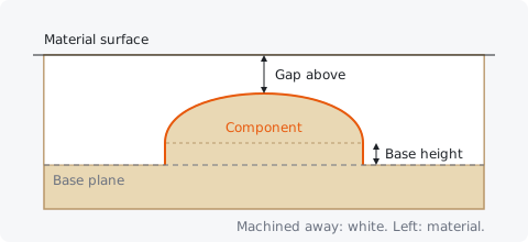
Each component's top sits a set distance below the material surface (its Gap above). New components are placed so their base sits on the model's base plane, the same zero plane the others share, so they come out level with what is already there. The model's base plane is as deep as the deepest component reaches; the Model section at the bottom of the tab tells you how deep that is.
Note: Each side of a double-sided job has its own relief. Switch side with
F6.
Create Components #
The Create Components palette holds the tools that make new components: Create Shape, Import Model, Two Rail Sweep, Extrude, From Image and Sculpt.
Most of them start from vectors you have drawn on the Drawing tab. Select the vectors first, then click the tool; its form replaces the palette until you click Close.
Create Shape #
Create Shape raises the selected closed vectors into a 3D shape with a flat, round or angled profile. Select one or more closed vectors, set the options and click Apply.
Nested vectors work the way they do for a pocket: a letter's hole stays a hole. Each Apply makes one new component from all the selected vectors.
Profile #
The profile is the shape of the cross section, from the edge of the vector inwards: Flat (a flat plateau at the height), Round (a dome) or Angled (a straight slope, like a roof).
| Profile | What you get |
|---|---|
| Flat | Vertical sides, flat top at Height |
| Round | A rounded dome; Angle is how steep its edge starts |
| Angled | A slope rising from the edge at Angle, meeting in a ridge or point |
Round and Angled shapes rise until they meet in the middle, so a wide shape comes out taller than a narrow one. Use Height to keep them in check.
Angle #
For a Round or Angled profile, the angle sets how steeply the shape rises from its edge (1 to 89 degrees). In the Rotate Components form it is the angle the components turn by.
A low angle gives a gentle, low shape; a high angle a steep, tall one. When rotating, quarter turns (90, 180, 270) are exact; other angles resample the component.
Height #
The height of a shape: for a Flat profile the height of its top, for Round and Angled the limit set by the Height choice. In Component from Image it is the height of the lightest pixels, and in Component Size the overall height of the selection.
For Round and Angled profiles the Height list chooses:
- No limit: the shape rises as high as its angle takes it.
- Limit to height: the shape is cut off flat at the height (a dome with a flat top).
- Scale to exact height: the whole shape is squashed or stretched so its highest point is exactly the height.
Base height #
A flat, straight-sided base added under the shape, so the shape stands on a step of this height. Leave it at 0 for a shape that rises straight out of the background.
The same option appears in Create Shape, Two Rail Sweep, Extrude, Component from Image and Component Properties. In Component Properties you can change the base of an existing component; in the 3D view you can also drag the amber base pin under a selected component up or down, which raises the shape out of the surface on a growing base.
Carve down #
Tick Carve down (invert) to cut the shape into the model instead of raising it: the same profile, upside down, like a stamp pressed into clay.
Two Rail Sweep #
Two Rail Sweep moves a cross section along two guide vectors (the rails), stretching it to fill the space between them. It is the tool for mouldings, picture frames, swords, leaves and anything with a constant profile that changes width.
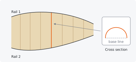
You need three vectors: two rails and one cross section, drawn as an open vector whose end points sit on its base line (an arch drawn on its side, say). For each row of the form, select the vector in the 2D view and click Use selection; the row then shows its name. Click Apply to make the component.
- The section's width is fitted between the rails at every point along them.
- Its height is measured from the straight line between its two end points.
- Two closed rails, one inside the other, sweep the ring between them (a frame).
Rail 1 and Rail 2 #
The two guide vectors the section runs between. Select a vector in the 2D view and click Use selection on the row to assign it.
The rails can converge and diverge; the section follows. Closed rails, one inside the other, make a closed ring such as a frame.
Cross section #
The vector that gives the profile of a sweep or an extrusion. Select it in the 2D view and click Use selection on the Cross section row.
Draw it as you want it to look cut through: its width across, its height up. Its height is measured from the line between its end points (or from its lowest point when it is closed).
Use selection #
Assigns the vectors selected in the 2D view to that row of the Two Rail Sweep or Extrude form (a rail, the drive curves or the cross section).
The row then names the vector it holds, or shows "(none)".
Scale height with rail distance #
When ticked (the default), the section gets taller where the rails are far apart and lower where they come together, so it keeps its proportions. Untick it to keep the section's drawn height all along.
Extrude #
Extrude runs a cross section along one or more drive curves at its drawn size. Use it for beads, ribs, raised lines and rope-like borders that keep the same width all the way.
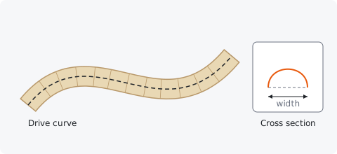
Assign the Drive curves and the Cross section with Use selection, then click Apply. The section's width becomes the width of the extrusion, centred on the drive curve; the section's left side (its low X) lies to the left of the curve's direction, which matters only for a section that is not symmetrical.
Drive curves #
The vectors the cross section is extruded along. You can assign several at once: select them all and click Use selection.
Open and closed vectors both work.
Component from Image #
From Image turns the selected picture into a relief: light pixels high, dark pixels low. It is a quick way to make textures, lithophane-style pictures and backgrounds from photos or height maps.
Import the picture first (File > Import Image...), select it in the 2D view, then click From Image (or Model > Component from Image...). The form shows the picture's pixel size and the size it covers on the material; the relief covers the same area.
| Option | What it does |
|---|---|
| Height | The height of white (or, inverted, black) pixels |
| Base height | A flat base added under it |
| Smoothing | Blurs the heights over this distance, to soften noise and pixel steps (0 = none) |
| Invert (dark pixels high) | Makes dark pixels high and light ones low |
| Transparent pixels leave no material | Pixels that are see-through in a PNG are left out of the component |
Smoothing #
Blurs the picture's heights over this distance before they become a relief, so pixel steps and photo noise do not show up in the carving. 0 turns it off.
A value of a few times the model's cell size is usually enough.
Invert #
Tick Invert (dark pixels high) for pictures where the dark parts should stand up, such as a dark drawing on white paper.
Transparent pixels leave no material #
With this ticked, pixels that are transparent in the picture are not part of the component, so only the opaque part makes a relief. Use it with PNG pictures that have a cut-out background.
Import 3D Model #
Import Model brings in an STL or OBJ mesh as a component. Carvio looks straight down on the model and keeps its top surface, so it can be carved from one side.
Click Choose file..., pick the file, set the size and click Import. A big file takes a moment; the status bar shows the import while it runs and the window keeps working. The model is centred on the material and gets the combine mode Merge High.
Anything the model hides underneath (an overhang, the inside of a cup) cannot be carved from above and is not kept. For parts that need both sides, see double-sided jobs.
Fit width #
The model is scaled so its width along X is this size, keeping its proportions. Leave it at 0 to make it 80% of the shorter side of the material.
Z base #
Lifts the imported surface by this much, so the model stands on a base of this height.
Sculpting #
Sculpt lets you shape a component by hand in the 3D view, with brushes that smooth, add, carve, flatten and push the surface. Select one component, click Sculpt and paint over it with the left mouse button.
While sculpting, left drag sculpts, Alt + left drag orbits about the point under the cursor and right drag pans. The brush shows as a circle on the surface. Each stroke is one undo step.
Sculpting works on one component at a time. If several are selected, the form offers Bake into one component. With nothing selected it offers a starting point:
- Component from visible model: a new component holding the whole visible model, to sculpt it all (the components it came from are hidden, not lost).
- Flat plane from selected vectors: a flat, zero-height component inside the selected closed vectors, to sculpt freely.
- Flat plane from material: the same over the whole material.
Brushes #
Pick the brush with the buttons at the top of the form. Every brush acts under the circle, strongest at its centre.
| Brush | What it does |
|---|---|
| Smooth | Evens out bumps and hollows |
| Smudge | Drags the surface along with the stroke, like a thumb through clay |
| Deposit | Adds material, building the surface up |
| Carve | Takes material away, digging the surface down |
| Flatten | Levels the surface towards a flat height |
Carve #
The Carve brush takes material away under the cursor, digging into the component while you drag.
Diameter #
The size of the sculpting brush. The circle on the surface shows it at the current zoom.
Strength #
How much each pass of the brush changes the surface, from 1% to 100%. Low values build up gently over several strokes; at full strength Smudge moves what is under the brush centre all the way with the cursor.
Keep inside its footprint #
Stops the brush from spreading material outside the component's current outline (in X and Y). Untick it to let Deposit and Smudge grow the component outwards.
Keep within its height range #
Keeps the heights between the component's lowest and highest points at the start of the stroke, so a stroke cannot push material above its top or below its bottom.
Bake into one component #
Merges the selected components into one, so they can be sculpted together. See Bake.
Component from visible model #
Makes a new component holding the whole visible model as it looks now. The components it was made from are hidden, not deleted, so the model does not change.
Flat plane from selected vectors #
Makes a flat, zero-height component filling the selected closed vectors: a blank to sculpt on.
Flat plane from material #
Makes a flat, zero-height component covering the whole material: a blank to sculpt on.
Component Tree #
The Component Tree lists every component and group of the model. Click one to select it, shift-click to select several; tick or untick its box to show or hide it.
The model combines the components in list order, top to bottom, so order matters for Subtract, Merge Low and Multiply. Groups show a fold arrow; unfold them to see what they are made of. The bin button on a row deletes that component or group.
You can also select components by clicking them in the 2D view or on the model in the 3D
view. Dragging a selected component moves it; the arrow keys nudge it by the grid spacing
(Shift for ten times as far, Alt for a tenth).
Note: A component on a hidden layer is left out of the model, the same as an unticked one. Hidden components are not machined.
Fold, Unfold and Delete in the tree #
The arrow in front of a group folds or unfolds it, to hide or show the components it is made of. The bin button at the end of a row deletes that component or group (a group with everything in it).
Deleting can be undone with Ctrl+Z. To delete several components at once, select them and
use Delete in Organise Components.
Component Properties #
The properties of the selected component: its name, how it combines with the others, its layer, where it sits in height, its base and its height scale.
The line under the fields sums it up: where its top sits relative to the material surface, its height and its size in grid cells.
Name #
The component's name, as the Component Tree shows it.
Combine #
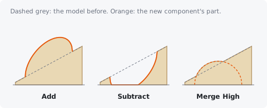
How the component joins the components above it in the list: Add, Subtract, Merge High, Merge Low or Multiply.
| Mode | Result |
|---|---|
| Add | Its heights are added on top of what is already there: a shape on a sloping background follows the slope |
| Subtract | Its heights are taken away: the shape is cut into what is there |
| Merge High | Wherever it overlaps, the higher of the two surfaces wins |
| Merge Low | Wherever it overlaps, the lower of the two wins |
| Multiply | The heights there are multiplied by its heights |
Add is the default for new shapes; imported models start as Merge High. Use Merge High when two shapes should meet without stacking, and Subtract to engrave one shape into another. Add and Merge components are placed by their Gap above; Subtract and Multiply are applied just as they are.
Layer #
The document layer the component belongs to. Hiding that layer on the Layers tab hides the component too, and leaves it out of the model.
Gap above #
How far the component's highest point sits below the material surface. 0 puts its top level with the surface; a negative value makes it stand above the surface, where the toolpaths simply cut it off flat.
Changing it moves the component up or down without changing its shape. The deepest component sets how deep the model goes (shown in the Model section).
Height scale #
Stretches or squashes the component's heights, in percent (100% = as made). Use it to make a model shallower to save machining time, or deeper for more drama.
Order #
Move up and Move down move the selected component in the list. Components combine in list order, top to bottom, so this changes what Subtract, Merge Low and Multiply act on.
Transform Components #
The Transform Components palette sizes, moves, aligns, rotates, mirrors and smooths the selected components. Groups are transformed as one.
You can also do most of this by hand: drag a component to move it; drag the handles of its selection box to size it; in the 3D view drag the pin above the box to change its height and the amber pin below it to raise or lower it.
Size #
Sets the width, depth and height of the selected components, scaled about the centre of their box. Tick Keep proportions to scale all three together.
Move #
Moves the selected components by the Offset X and Offset Y you type, when you click Apply. Centre on material puts them in the middle of the material at once.
Centre on material #
Moves the selected components so they are centred on the material.
Align #
Lines the selected components up with the material or with the selected vectors: choose which in Align to, then click Left, Centre X, Right, Bottom, Centre Y, Top or Centre in both directions.
Rotate #
Turns the selected components about their centre by the Angle: Rotate CW turns them clockwise, Rotate CCW counter-clockwise. Quarter turns are exact; other angles resample the component.
Mirror #
Flips the selected components in place: Mirror X flips left to right, Mirror Y top to bottom.
Smooth #
The Smooth button smooths the selected component a little each time you click it, softening sharp edges and noise. In the Sculpting form, Smooth is the brush that evens out bumps under the cursor.
The Smooth button works on one component (not a group; bake a group first). Model > Smooth Selected Component and Smooth on a component's right-click menu do the same.
Organise Components #
The Organise Components palette groups, bakes and deletes components, makes vectors from them, cuts them with vectors and exports them.
Group and Ungroup #
Group puts two or more selected components into a group that moves and sizes as one; Ungroup dissolves the selected group again. Nothing changes shape.
Inside a group the components still combine with their own modes; the group then combines with the rest of the model with its own mode.
Bake #
Bake merges the selected components (or a group) into one single component, combined the way they look now. You need to bake before you can sculpt several components as one.
Baking cannot be taken back except with Undo, so keep a copy if you may want the parts later.
Delete #
Deletes the selected components. Del does the same when components are selected and no
vectors are.
Model > Delete Selected Component does the same. Undo (Ctrl+Z) brings deleted
components back.
Boundary Vectors #
Draws closed vectors around the outline of the selected components. Use them for a profile cut-out around a model, or as the boundary of a 3D toolpath.
Cut by Vectors #
Splits a component with closed vectors: the part inside the vectors becomes a new component. Select the component and the closed vectors, choose what happens to the inside and click Cut.
| Choice | Result |
|---|---|
| Moves to a new component | The inside becomes a new component; the original keeps the rest |
| Is copied to a new component | The original stays whole; the new component is a copy of the inside |
| Is deleted | The inside is removed; nothing new is made |
A group is baked into one component first.
Export #
Saves the selected component as an STL or OBJ mesh: a closed solid with the component's surface on top and a flat base underneath, ready for a 3D printer or another program. Several selected components are exported combined into one mesh.
The file is named after the component; the status bar reports the triangle count and size when it is saved. Very large components are sampled more coarsely to keep the file a reasonable size. File > Export Component... does the same.
Export Clipart #
Saves the selected components into the clipart library, so you can drop them into other jobs.
Model #
The Model section at the bottom of the tab tells you how deep the model goes: the distance from the material surface down to the model's base plane, the overall height of the combined model and the size of its grid.
From relief to toolpaths #
The 3D Roughing and 3D Finishing toolpaths machine the combined model as you see it: every visible component on a visible layer, with its combine mode, gap and height scale.
- Build the model on this tab.
- On the Toolpaths tab, make a 3D Roughing toolpath with a larger tool to clear the bulk of the material, leaving a small allowance.
- Make a 3D Finishing toolpath with a ball nose tool and a fine stepover for the final surface.
- Preview them (Toolpaths > Preview Toolpaths...) to see the result.
Both toolpaths can be limited to the material, the model's outline or selected vectors (their Boundary option). When you change the model afterwards, the 3D toolpaths are marked out of date; recalculate them before you save the G-code.
Tip: Anything that stands above the material surface (a negative Gap above) is cut off flat at the surface: the material simply is not there.