
Special Toolpaths #
Besides profiles, pockets, drilling and V-carving, Carvio has six toolpaths for particular jobs: Fluting for grooves that taper in and out, Edge Form for running a shaped cutter along an edge, Moulding for sweeping a drawn profile along a rail with a ball nose, Prism Carving for bevelled, raised shapes, Texture for a hand-carved look, and Inlay for pockets and the pieces that fit them.
You find them on the Toolpaths tab (the Fluting, Prism, Inlay, Texture, Edge Form and Moulding buttons) and on the Toolpaths menu. Like the other toolpaths, select the vectors first, open the form, set the options and click Calculate. The options they share with the other forms, such as Start depth, Cut depth, the Tool and its Tool Settings, are described in the toolpaths chapter.
Fluting #
A fluting toolpath follows the selected vectors on the line with the depth ramping in at the start, out at the end, or both. Use it for the flutes on columns and pilasters, reeding, and any groove that should fade in and out of the surface.
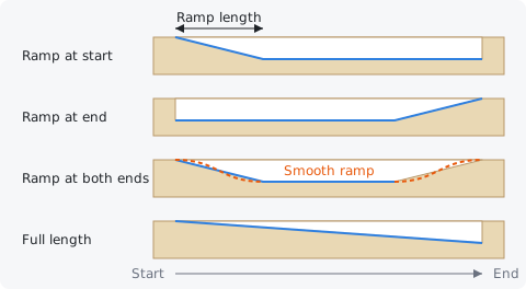
Each vector is cut on the line, starting from its first point. The flute starts at the Start depth and goes down to the Cut depth along the ramp, so a ball nose or core box bit leaves a groove that narrows to nothing at the ramped end, and a V-bit leaves a pointed one. When the cut depth is more than the tool's pass depth, the whole flute (ramps included) is repeated at evenly spaced, deeper levels, each pass ramping from the start depth down to its own depth.
Fluting is meant for open vectors (lines and curves). A closed vector is followed once all the way round from its start point back to it.
Tip: For evenly spaced flutes, draw one line, then use Array on the Drawing tab to copy it. Every flute then gets exactly the same ramps.
Ramp #
Where the depth changes along each flute: No ramp (full depth from end to end), Ramp at start, Ramp at end, Ramp at both ends, or Full length (the depth grows steadily over the whole flute, deepest at the end).
With No ramp and Ramp at end the tool plunges straight to depth at the start. With Ramp at start, Ramp at both ends and Full length it touches down at the start depth and slopes into the cut, which is gentler on the tool and gives the classic tapered flute end. Ramp at both ends is the usual choice for columns.
Ramp length #
How far along the vector the ramp runs, from the start depth to full depth. It appears for the start, end and both-ends ramps.
A ramp can never be longer than the flute: with Ramp at both ends each ramp is limited to half the vector's length, so a short flute becomes a smooth dip with no flat part. For column flutes, a ramp of 2 to 4 times the tool diameter looks natural.
Smooth ramp #
Shapes the ramp as a gentle S-curve instead of a straight slope: the depth eases out of the surface and eases into the full depth.
A smooth ramp gives a rounded, teardrop-like flute end with no visible corner where the ramp meets the flat bottom. Turn it off for a straight taper (for example, a crisp chamfered end with a V-bit). It is on by default.
Forward #
Cuts each vector in the direction it was drawn, from its first point to its last.
The ramps follow the cutting direction: Ramp at start is at the vector's first point when you cut forward.
Reverse #
Cuts each vector backwards, from its last point to its first.
Use it to move a one-sided ramp to the other end without redrawing the vectors, or to make all flutes run the same way when some were drawn the other direction.
Edge Form #
An edge form toolpath runs a form tool along the selected vectors at one height, its cutting part reaching sideways into the edge. Use it for mouldings with a shaped cutter, slots with a T-slot or keyhole cutter, dovetails and undercuts.
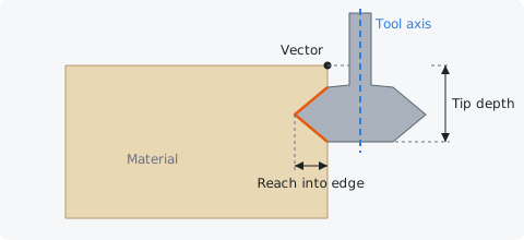
Unlike a profile, the tool does not step down: its tip stays at the Tip depth the whole way, and the cutter's shape makes the shape of the edge. If you ask for several Passes, the tool works its way into the edge sideways instead. The cutter's shape comes from the form tool's profile in the Tool Database (Tool type: Form Tool, then Design profile...); without a profile it cuts like a flat end mill of its diameter.
Because a cutter that undercuts (a T-slot, dovetail, keyhole or lollipop cutter) cannot be plunged into solid material, the tool normally goes down to its height outside the cut, at the end of a lead, and comes in sideways. Give it room: start the vectors near the stock edge, or clear the way in with another toolpath first. A keyhole or T-slot cutter with a cutting bottom can also plunge at the start.
Warning: Check the form tool's diameter and profile carefully in the Tool Database and watch the preview. An undercut cutter that is lifted or plunged in the wrong place will break or tear the work.
Tip depth #
How far below the surface the tool's tip runs. The whole toolpath runs at this one height.
For a moulding cutter, set it so the profile sits where you want it on the edge: the tip depth minus the height of the cutter's profile is where the shape starts at the top. For a slot cutter it is the depth of the bottom of the slot. With Project onto the machined surface on, it is measured from the stock as the earlier toolpaths leave it.
Reach into edge #
How far the cutter's widest part reaches past the vector into the material. 0 just touches the edge; the tool's radius puts the tool's axis on the vector.
The tool's axis runs at its radius minus the reach (plus any Allowance) away from the vector, on the side the Tool stays on. The reach can never be more than the tool's radius. For a moulding on the edge of a board, draw the vector on the board's edge and set the reach to how deep the profile should cut in: for example 6 mm for a 6 mm round-over.
It has no effect with On the line (slot), where the axis follows the vector.
Passes #
The number of passes the tool takes to reach into the edge. The reach grows evenly on every pass, all at the same tip depth.
With a reach of 6 mm and 3 passes, the tool cuts 2 mm, 4 mm and then 6 mm into the edge. Use more passes for a large profile or hard material, so the cutter takes a light bite each time. With On the line (slot), each pass repeats the same path.
Form tool #
The cutter that shapes the edge. Pick a tool of type Form Tool from the Tool Database; Carvio warns you when the selected tool is something else.
Carvio comes with several form tools to start from (a T-slot cutter, a keyhole cutter, a dovetail, cove, half-round, round-over, a classical moulding and a lollipop cutter). To match a cutter you own, open the tool in the Tool Database and use Design profile... to draw its half-section, from a vector or a preset. The tool's feeds and speeds are shown under Tool Settings below the row.
Tool stays #
Which side of the vector the tool runs on: Outside / Right keeps it outside a closed vector (to the right of an open one), Inside / Left keeps it inside (to the left), and the material it cuts into is on the other side.
For a moulding round the outside of a tabletop, draw the top's outline and choose Outside / Right: the tool stays off the board and reaches in by the Reach into edge. For a profile round the inside of a frame opening, choose Inside / Left. "Right" and "left" for an open vector are as seen looking along the direction the vector was drawn.
On the line (slot) #
Runs the tool's axis exactly along the vector, so the cutter makes a slot centred on the line, as wide as the cutter at each height.
Use it for T-slots, keyhole slots for hanging, and dovetail grooves. Reach and allowance do not apply. Together with Plunge at the start it makes a keyhole slot in the middle of a board.
Climb and Conventional #
The direction the tool travels along the edge. Climb is the usual choice on a CNC router: the edge comes out cleaner and the tool is pulled into the cut less. Conventional runs the other way.
This works like the Climb and Conventional options of a profile. On the line the cutter cuts on both sides at once; the option then just picks the direction along the vector.
Plunge at the start #
Instead of coming in from a lead, the tool goes straight down at the start of the vector to the tip depth, runs along it, comes back along the same path and lifts out through the hole it plunged. This makes a keyhole slot in the middle of a board.
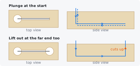
The entry hole is the blade's full diameter, so draw the vector to start where the hole should be. A closed vector is followed once round and the tool lifts out at the start. Plunging needs a cutter with a cutting bottom (a keyhole or T-slot cutter), which Carvio reminds you of when this is on.
Lift out at the far end too #
With Plunge at the start on, the tool lifts straight out at the far end instead of coming back, cutting a second hole on its way up: a slot with a hole at both ends (O—O).
The climb out at the far end is a cutting move at the plunge rate, up to just above the surface. It is only used on open vectors; a closed vector always lifts out at the start.
Lead in / out #
How far outside the cut the tool goes down to its height and comes back out. It is shown when Plunge at the start is off.
On a closed vector the tool enters straight in from the free side (away from the material) at the start point, goes once round and leaves the same way. On an open vector the cut is extended straight on along the line's direction before the start and past the end. The tool descends at the lead point, so make the lead long enough that this point is clear of the stock, or in an area that is already cleared, for example 10 mm (the default) plus the tool's radius from the stock edge.
Allowance #
Material left on the edge by this toolpath. A positive value moves the tool away from the edge, a negative one cuts further in.
Use a small allowance (0.2 to 0.5 mm) for a roughing run, then a second toolpath with 0 to finish the edge cleanly. Like the reach, it does not apply to On the line (slot).
Clear chips by backing out of the cut #
Every so often, the tool backs out along everything it has cut to the entry, lifts out, comes back the same way and carries on. A slot or undercut cutter cannot lift out of its cut anywhere else, so this is how it gets rid of the chips packed around it.
All cutting is counted, in any direction: the plunge, the run along the vector, the way back and the climb out at the far end. A deep plunge is pecked the same way. When the tool came in from a lead, it backs out to the lead point and rises there. Turn this on for deep keyhole slots and T-slots, especially in hardwood or plastics where chips weld together.
Every #
The cutting distance between chip clearings, when Clear chips by backing out of the cut is on.
Shorter distances clear more often and take longer. Start with 2 to 3 times the cutter's diameter (the default is 20 mm) and shorten it if you hear the cutter labouring.
Moulding #
A moulding toolpath sweeps a profile (a cross section you draw) along one or more drive rails. Use it for picture frames, door and cabinet mouldings, curved trims and raised edges, cut with an ordinary ball nose instead of a shaped router bit.
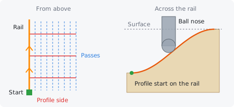
Draw the rail where the moulding should run and the profile anywhere in the job, as an open vector seen from the end of the moulding: across is the distance from the rail, up is the height. Then select the rail (or several rails), Shift-click the profile last, open Toolpaths > Moulding..., set the options and click Calculate. The last vector you select is always the profile.
The profile's start point hangs on the rail's start point and the profile goes off to the right of the rail, looking along the direction the rail was drawn. Round a closed rail it always hangs on the outside, so for a frame draw the rail on the inside edge (the opening) and the profile from there outward. While the form is open, the rails show in orange with a green square at their start, arrows along their direction and red lines on the side the profile hangs on; the profile's start point shows as a green square too. Use Reverse Rail and Reverse Profile to change them.
The finishing tool runs passes that follow the rail, stepping across the profile by the tool's Stepover; each pass is at the height where the tool touches the profile, so a ball nose leaves the profile's exact shape (with the usual small scallops between passes). Along an open rail the passes go back and forth: at the end of a pass the tool lifts a little (at least a stepover above the profile), steps over and comes back down. Round a closed rail every pass is a loop in the rail's direction. A moulding is a 2.5D toolpath: it needs no 3D model, and the preview shows the result.
Tip: A moulding takes many passes. Rough it first with Use Larger Area Clearance Tool, and give the ball nose a stepover of about 10% of its diameter for a smooth finish.
Drive Rail #
The vectors the moulding follows, and the profile. Select the rails first and the profile last; the form says how many rails it found and how wide and high the profile is.
Rails can be open or closed, lines, arcs or curves. The profile must be an open vector; a closed one is refused. Each rail gets the same profile, so several frames or trims can be cut with one toolpath. A rail or a profile that crosses itself makes passes that overlap, so keep them clean.
Reverse Rail #
Reverses the direction of the selected drive rails. On an open rail the start point moves to the other end, so the profile hangs on the other side; on a closed rail it only changes the direction the passes run.
The vectors themselves are reversed (Edit > Undo puts them back), so the toolpath keeps the change when it is recalculated.
Reverse Profile #
Reverses the profile vector, so its other end is the one that hangs on the rail. Use it when the profile comes out mirrored: its tall side where the low side should be.
Toolpath Position #
Where the profile sits in the material's thickness. Gap Above Toolpath is the distance from the material top down to the profile's highest point; Gap Below Toolpath is the distance from the material bottom up to its lowest point.
With a gap above of 0 the top of the profile is at the surface, which is right for a moulding cut into the face of a board. The profile keeps its drawn height either way: to make it taller or shorter, scale the profile vector.
Cut Depth #
How far below the material top the profile's lowest point lies: the gap above plus the profile's height. It is shown, not set.
If the profile does not fit in the material, the form says so. Change the gap, the material thickness in Job Setup, or the profile vector. With Rest machining on, the part of a too-tall profile that lies above the material top is simply left out of the toolpath instead of being cut in the air.
Vary Stepover #
Spaces the passes evenly along the profile's surface instead of evenly across it, so steep parts of the profile get as many passes as flat ones.
Without it, a nearly vertical part of the profile gets only a pass or two and comes out ridged. With it, the toolpath has more passes and takes longer, but every part of the profile has the same finish.
Skip Flat Regions #
The finishing tool leaves out the passes that would only run over the profile's flat parts, because the clearance tool already cut them to depth. It can only be ticked with Machine Flat Regions on.
Only passes where the ball nose rests on a flat, inside the part the clearance tool's flat bottom cut, are skipped; the passes near the edges of a flat still run.
Use Larger Area Clearance Tool #
Roughs the moulding with a second, larger tool first. It makes a separate toolpath, named like this one with [Clear] added, listed (and run) before the finishing toolpath.
The clearance tool cuts in levels of its Pass depth, each level a set of passes that follow the rail, as deep as it can go without cutting into the profile plus the Machining Allowance. It never cuts further past the profile's ends than the finishing tool reaches. Pick the tool in the row below the option; an end mill of several times the ball nose's diameter is usual.
Machine Flat Regions #
The clearance tool also cuts the profile's flat (horizontal) parts to their true depth, without the machining allowance, so the finishing tool does not have to.
The flats are cut where the clearance tool fits on them. With Skip Flat Regions the finishing tool then leaves them alone.
Ramp Plunge Moves #
The clearance tool ramps down into each level instead of plunging straight down: back and forth along the pass on an open rail, along the loop on a closed one, over the Distance given.
Use it with end mills that do not plunge well, or in hard material. The finishing tool always comes straight down onto the profile.
Machining Allowance #
The thickness of material the clearance tool leaves on the profile for the finishing tool to remove. It applies to the clearance toolpath only.
0.5 mm is a good start. A larger allowance protects the profile from a clearance tool that deflects; flats cut with Machine Flat Regions get none.
Create Sharp Corners #
Makes the moulding meet in a mitre at the rail's corners, like two lengths of moulding cut and glued at 45°. Without it, the moulding rolls round each corner. This is the setting for every corner you have not picked with Pick Corners.
It works on both kinds of corner:
- An outside corner points away from the moulding (the corners of a frame's outer edge). Rolled, the profile turns round the rail's corner point in an arc; mitred, the passes meet in a point.
- An inside corner points into the moulding (the corner of an L, or an open rail turning towards the profile's side). Rolled, the profile's far edge stays sharp and the passes nearer the rail curve round it; mitred, every pass meets in a crease along the mitre line.
Very sharp corners (under about 30°) are bevelled rather than run out to a long point.
Below the checkbox a line counts the rail's corners: how many are sharp and round, and how many are inside and outside.
Pick Corners #
Sets corners one by one. Click Pick Corners, then click a corner of a drive rail in the 2D view to switch it between sharp and round. The corners show on the rails while the form is open:
- a square is a sharp (mitred) corner, a circle a round (rolled) one;
- blue marks an inside corner, purple an outside one.
The corner under the mouse gets a ring, and the status bar says which kind of corner you switched and what it is now. Clicks do not select or move anything while picking; pan with the middle button, Space and drag, or the right button. Click Done to finish, then Calculate.
Picked corners are saved with the toolpath and found again by their position on the rail. If you move a rail's node, that corner goes back to the Create Sharp Corners setting.
Reset Corners #
Forgets every picked corner, so all of them follow Create Sharp Corners again.
Boundary Offset #
How far past each end of the profile the tool's centre goes. With 0 the tool's centre stops at the profile's ends, so a steep or vertical end is not cut fully.
To cut a vertical end clean, give an offset of at least the tool's radius plus about 10%. Past an end the surface continues level at the height of the end's lowest point, so the tool cuts that level there.
Use automatic boundary offset #
Works out the boundary offset for you: a little more than the tool's radius past an end that the tool could not otherwise finish (a steep or vertical end), and nothing past one it can. The Boundary Offset value is ignored while this is ticked.
Prism Carving #
Prism carving cuts V-bit bevels that rise from the outline of the selected closed vectors towards their middle, meeting in a sharp ridge where the shape is narrow and leaving a flat top where it is wide. It gives letters and shapes a chiselled, pyramid-like look.
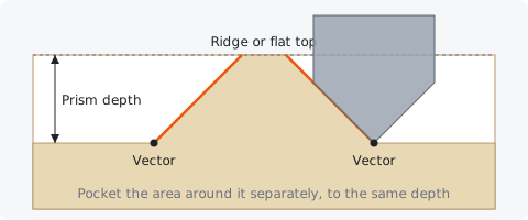
The vector outline is the base of the prism, at the Prism depth below the surface. The bevels rise inward at the V-bit's half angle (45° for a 90° bit, 30° from vertical for a 60° bit). Each depth pass runs on an inward offset so the bit's edge stays on the final bevel. A shape whose half-width is less than the prism depth times the slope comes to a ridge below the surface; a wider one keeps a flat top at the surface (or at the Start depth).
Prism carving only cuts the bevels. To make the prism stand up, clear the area around it with a separate Pocket toolpath to the same depth, for example between the vectors and a border around them. Open vectors are skipped.
Prism depth #
How far below the surface the base of the prism lies: the depth of the vector outline, where the bevels start.
The deeper you go, the higher the bevels rise and the more shapes close into a ridge. When it is more than the tool's pass depth, the bevels are cut in several evenly spaced passes. Use the same depth for the pocket around the prism.
V-Bit #
The V-bit that cuts the bevels. Its included angle sets the slope of the bevels, and a flat tip, if it has one, is allowed for.
Carvio warns you when the selected tool is not a V-bit or engraving tool. A 90° bit gives low, wide bevels; a 60° bit gives steeper, taller ones.
Texture #
A texture toolpath covers an area with random, overlapping strokes of a ball nose scooping in and out of the surface, for a hand-tooled or adzed look on panels, signs and backgrounds.
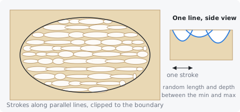
The strokes run along parallel lines across the boundary. Along each line, each stroke has a random length between the Min cut length and the Max cut length and a random depth between the Min cut depth and the Max cut depth. A stroke starts at the surface, dips smoothly to its depth in the middle and rises out again; between strokes on one line the tool travels just above the surface. The pattern is random but repeatable: the same Random seed always gives the same strokes.
A ball nose gives the softest scoops (Carvio suggests one when you pick another tool). Depths are measured from the Start depth, or from the machined surface with Project onto the machined surface.
Min cut depth #
The shallowest a stroke can go, below the start depth. Each stroke picks a random depth between this and the Max cut depth.
Keep some difference between the two: equal depths make every scoop alike.
Max cut depth #
The deepest a stroke can go, below the start depth.
With a ball nose, depth also sets how wide each scoop is. For a 6 mm ball nose, depths from 0.5 to 1.5 mm (the defaults) give a gentle texture; go deeper for a bolder, rougher one.
Min cut length #
The shortest a stroke can be. Each stroke picks a random length between this and the Max cut length.
Short strokes look like chip carving or hammered metal; long ones look like an adze or a gouge drawn along the grain. The defaults are 10 and 30 mm.
Max cut length #
The longest a stroke can be.
The more the minimum and maximum differ, the more irregular the texture looks.
Max overlap #
How much neighbouring lines of strokes may overlap, as a percentage of the tool diameter. It sets the spacing of the lines: the tool diameter less this percentage.
At 50% (the default) a 6 mm tool runs its lines 3 mm apart. More overlap packs the strokes closer and leaves less of the original surface; less overlap leaves ridges of untouched surface between the lines.
Variation #
How random the pattern is, as a percentage. It varies the spacing between lines and how much each stroke overlaps the one before it on the same line.
At 0% the lines are evenly spaced and the strokes follow each other end to end. Around 50% (the default) looks hand-made; at 100% the spacing changes by up to 40% from line to line and strokes overlap by up to half their length.
Angle #
The direction of the lines of strokes, in degrees. 0° runs them along X, 90° along Y.
Run the strokes along the grain of the wood for a natural adzed look, or across it for a bolder one.
Use selected closed vectors as boundary #
When on, the texture fills the selected closed vectors; when off, or when no closed vector is selected, it covers the whole material.
Vectors inside other vectors make holes, so you can texture the background around raised lettering by selecting a border and the letters together. Open vectors are skipped.
Boundary offset #
Shrinks the boundary inward by this distance before the strokes are laid out. The boundary limits the tool's centre, so a scoop near the edge still spills out by part of its width.
Set it to about the tool's radius to keep the scoops inside the boundary, or leave it at 0 to texture right up to (and a little over) the edge.
Random seed #
The starting number for the random pattern. The same seed always gives the same strokes; change it to get a different pattern with the same settings.
Use this when you like the overall look but not one particular area, or to give matching panels different textures.
Inlay #
The inlay toolpath cuts both halves of an inlay from the same vectors: the female pocket in the base board and the male piece in the inlay wood, left standing with a band cleared round it. With a V-bit the walls slope so the halves wedge tight (a V-carve inlay); with an end mill they are straight.
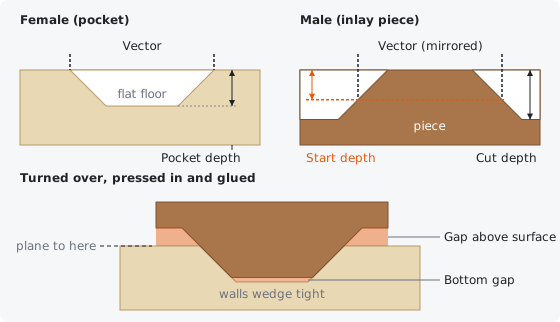
Make two toolpaths from the same vectors: one with Inlay type Female in the base board, and one with Male in the inlay wood (as another job, or on another sheet of this one, on the Layers tab). Turn the male piece over, glue it into the pocket and plane or sand the backing away. The male piece is mirrored for you (Mirror male piece), so lettering and other lopsided shapes match once it is turned over.
Use the same tool, depth and gaps for both halves: the male toolpath works out its depths from the female's Pocket depth.
Tip: The Inlay Wizard does all of this for you: it checks that the two copies match, picks the settings, shows how the halves fit in a cross-section, and makes both toolpaths at once.
Inlay strategies #
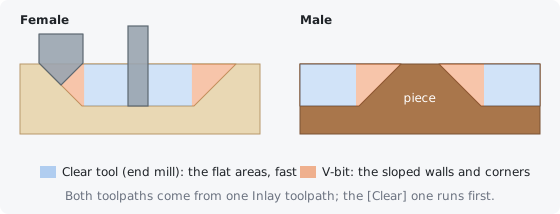
The tool you pick decides the kind of inlay, and a Clear tool can be added to either kind to hog out the flat areas quickly.
| Strategy | Tool | Clear | Fit and corners | Best for |
|---|---|---|---|---|
| V-carve inlay | V-bit | None | Sloped walls wedge tight, sharp corners | Small designs, lettering |
| V-carve inlay with clearing | V-bit | End mill | Same fit; the end mill clears the floors | Larger designs, deeper pockets |
| Straight-walled inlay | End mill | None | Straight walls, inside corners rounded | Simple shapes with round corners |
| Straight-walled with clearing | End mill | Larger end mill | Same fit; the big tool clears first | Large pockets and wide bands |
Tip: For most inlays use a 60 or 90 degree V-bit with a 3 or 6 mm (1/8 or 1/4 inch) end mill as the Clear tool: the V-bit makes the crisp, tight walls and corners, the end mill does the bulk of the cutting in a fraction of the time.
V-carve inlay #
With a V-bit both halves are V-carved with a flat depth: the walls slope at the bit's angle, so the piece wedges into the pocket and closes every gap, and the corners stay sharp.
- Female: a V-carve of the vectors with a flat floor at the Flat depth. Narrow parts are carved to a V and are shallower, just like a V-carve with a flat depth.
- Male: the piece is the vector shape (less the Side glue gap) at the start depth, tapering to its top above it and spreading out below it, with the band round it cleared to the cut depth. The form shows both depths.
- Start depth = Pocket depth − Bottom gap − Side glue gap ÷ tan(half the bit's angle). It is the depth the piece goes into the pocket, so the bottom gap stays under it.
- Cut depth = start depth + Gap above surface + the side gap term, so when the piece is pressed home its backing stays that gap above the base board.
The bit must be big enough for the cut depth: its cone ends at half its diameter ÷ tan(half its angle) deep (6.35 mm for a 12.7 mm 90 degree bit). The form warns when it is not.
Saw the male piece free in the cleared band, outside the foot of its sloped walls: the waste beyond the band stands at full height and would hold the piece off the board.
Tip: Press or clamp the piece in with plenty of glue: the sloped walls squeeze it out and pull the joint tight. Then plane or sand down to the base board's surface.
Clearing with an end mill #
Pick an end mill as the Clear tool to hog out the flat areas (the female floor and the male band) before the main tool. It gets its own toolpath, named with [Clear] on the end and placed first.
With a V-bit, the end mill clears the flat floors down to the pocket or cut depth in passes of its own pass depth, and the V-bit then only cuts the sloped walls, the corners and whatever the end mill could not reach. Without one, the V-bit clears the floors itself, which is slow and leaves fine ridges.
With an end mill as the main tool, a larger end mill clears first and the main tool cleans up the corners and walls, as described under Clear.
Straight-walled inlay #
With an end mill the female pocket and the male piece have straight walls. It is simple and works with any end mill, but needs a little care at the corners.
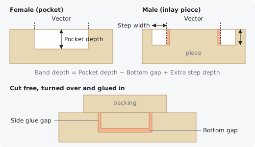
The female pocket is an ordinary pocket (offset clearing with a final pass round the wall) to the Pocket depth. The male piece is the vector shape shrunk by the Side glue gap; the band around it is cleared with offsets, finishing with a pass round the piece's wall. Saw the piece free through the band.
The tool's radius rounds the pocket's inside corners, but the male piece's outside corners stay sharp, so the piece will not fit there. Give sharp outside corners of your design a radius at least as big as the tool's, use a small tool, or use a V-bit.
Inlay type #
Female (pocket) cuts the pocket for the inlay inside the vectors. Male (inlay piece) leaves the inlay piece standing and clears a band around it.
Make one toolpath of each from the same vectors, with the same tool and settings. See Inlay strategies for how the tool changes the cut.
Pocket depth / Flat depth #
How deep the female pocket is. Use the same value for the male toolpath: its depths are worked out from it. With a V-bit it is called Flat depth, as in the V-Carve toolpath: the pocket is V-carved, and where the design is wider than the bit's cone reaches at this depth the V-carve stops and the floor is flat (cleared by the Clear tool). Narrow parts are just V grooves, shallower than this. A shallower flat depth needs less inlay wood and keeps the male cut inside the bit's cone; a deeper one makes thicker inlay walls.
With an end mill the male piece stands the pocket depth less the Bottom gap high. With a V-bit it goes that far into the pocket (see V-carve inlay). 3 to 5 mm is typical. Both are cut in passes no deeper than the tool's pass depth.
Side glue gap #
The clearance between the male piece's walls and the pocket's walls. The male piece is the vector shape shrunk by this much on every side.
It is applied to the male piece only: the female pocket is cut to the vectors exactly. With an end mill, 0.05 to 0.15 mm (the default is 0.1 mm) gives a snug fit with room for glue; go up a little if the piece will not go in. With a V-bit the walls close up as the piece is pressed in, so the gap only lets the piece sink a little deeper; the start depth allows for it.
Bottom gap #
Space left under the male piece for glue and so that the piece is never held off by the pocket floor. The male piece reaches the Pocket depth less this much.
The default 0.5 mm works for most woods. It is shown for the male type only.
Step width #
How wide the cleared band around the male piece is, measured outward from the vector.
With an end mill the band gives you room to saw the piece free and lets the backing sit flat on the base board; it is made at least as wide as the tool. With a V-bit it is widened when needed so the band has a flat floor round the foot of the piece. The default is 10 mm.
Extra step depth #
End mill male only: cuts the band around the piece this much deeper than the piece's height, so the piece stands taller by the same amount.
The band is cleared to the pocket depth less the bottom gap plus this. Keep in mind that a taller piece reaches further into the pocket: with the backing on the surface, the gap under it becomes the Bottom gap less this amount. Leave it at 0 (the default) unless you want a deeper band, for example to make sawing the piece free easier.
Gap above surface #
V-bit male only: how far the male piece's backing stays above the base board when the piece is pressed into the pocket. It sets how deep the band around the piece is cut.
The gap lets the sloped walls close up before the backing touches the board, and leaves room for squeezed-out glue. 1 to 3 mm is typical (the default is 2 mm); it is planed away with the backing.
Mirror male piece #
Mirrors the male piece left to right, so it matches the pocket once it is turned over to be glued in. Leave it on unless the vectors are already mirrored.
Symmetric shapes such as squares and circles come out the same either way; lettering and other lopsided shapes only fit when mirrored. The piece is mirrored about the middle of the vectors, so it stays where it was drawn.
Clear #
An end mill that clears the flat areas (the female floor and the male band) before the main tool. Leave it at None to let the main tool do all the cutting.
It gets its own toolpath, named with [Clear] and placed first. With a V-bit, the V-bit then only cuts the walls and corners (see Clearing with an end mill). With an end mill as the main tool, the Clear tool must be larger than it to be used.
Clear strategy #
How the clearance tool clears the flat areas of a V-carve inlay: Offset rings that follow the shape, or Raster lines along X.
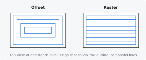
Offset suits letters and curved shapes; raster can be quicker on large, blocky areas.
Inlay Wizard #
Makes both halves of an inlay in one go from two copies of a design: it checks the copies match, picks the settings for a tight inlay, shows how the male piece will sit in the pocket, tells you when it won't fit, and makes the female and male toolpaths together. It works with a V-bit (a V-carve inlay) or an end mill (a straight-walled inlay).
- Draw (or import) the design, and copy it: one copy for the pocket in the base board, one for the inlay piece. Leave the male copy as drawn; the wizard mirrors it for cutting.
- Select the two copies, the female (pocket) copy first. Each copy can be grouped, sit inside an outline vector, or be a single vector; copies are told apart by not overlapping.
- Open the Inlay toolpath and click Inlay Wizard... (the wand) at the top of its form.
- Check the settings and the fit, then click Create Toolpaths.
The wizard compares the copies. When they are the same shape it says so; when the male copy is already a mirror image it is cut as drawn instead of being mirrored again. When the copies differ, the pocket and the piece will not fit: copy the female design again for the male.
Copies #
How many vectors make up each copy, and whether the two copies are the same shape. The female copy is cut as the pocket in the base board, the male copy as the inlay piece. When the copies differ the wizard says so: the piece will not fit the pocket.
Swap #
Swaps the copies: the one used for the pocket becomes the inlay piece and the other way round.
The female copy is the one holding the vector you selected first.
Tool #
The bit both halves are cut with. A V-bit gives sloped walls that wedge tight and keep sharp corners. An end mill gives straight walls: the pocket's inside corners come out rounded to the bit's radius, while the piece's corners stay sharp, so a design with sharp corners won't go in unless its corners are rounded at least that much. The wizard starts with the Inlay form's tool when it is a V-bit, else the library's first V-bit; pick an end mill here for a straight-walled inlay.
Auto settings #
Picks the settings for the design and the tool again: the pocket depth, the gaps, the step width and a clearance end mill. The wizard does this when it opens; click it again after changing the tool or to undo your own changes.
With a V-bit, the Flat depth is made only as deep as the widest part of the design needs, plus the Bottom gap (0.5 mm), and never deeper than the bit's cone can cut. Lettering then needs the least inlay wood. The Side glue gap is 0.1 mm, the Gap above surface 2 mm (less when the bit's cone is too short), and the Step width wide enough for the male's walls.
With an end mill, the pocket depth stays as it is (4 mm when none is set), the Bottom gap is 0.5 mm, the Extra step depth 0, and the Step width at least the bit's diameter plus 2 mm.
The clearance tool is the largest end mill, up to 6.35 mm (1/4 in), that fits the band round the male piece (for an end mill inlay, only one larger than the inlay's bit).
Then it tries these settings on the fit check, and when the piece won't fit it changes them until it does, and says what it changed:
- V-bit: a piece resting on the pocket floor gets more Bottom gap, a backing that lands on the board gets more Gap above surface (or a shallower Flat depth when the bit's cone is too short), and walls that clash get a little more Side glue gap.
- End mill: it tries Side glue gaps of 0.1 to 0.3 mm with your end mill and then with up to three smaller end mills from the tool library, then larger gaps (up to the bit's radius). An end mill's pocket has rounded corners, so the piece's sharp corners need room round them.
When nothing fits it says so; then try a V-bit or round the design's corners. Change any setting afterwards; the fit check follows.
Fit check #
Cuts both halves on the computer, turns the male over and presses it into the pocket until it touches, and reports how they fit.
It says Fits when the piece goes in as far as the settings mean it to: for a V-bit until the walls meet and fill the pocket at the surface, for an end mill all the way to the pocket floor (or until its backing is on the board). Otherwise it says Won't fit, how far short the piece stops, and marks in red on the view of the design where the piece hits the pocket. For an end mill these are usually the corners: round the design's corners to at least the bit's radius, raise the Side glue gap, use a smaller end mill, or a V-bit.
- Male face sits ... into the pocket: how far the piece goes in.
- Pocket filled at the surface: how much of the pocket's outline the piece fills where the surface is planed. The walls meeting gives close to 100%; the last percent or two is the check's own grid.
- Glue gap under the piece and backing above the surface: the room left for glue under the piece, and between the male's backing and the base board.
With a V-bit it also warns when the backing would land on the board before the walls meet (raise Gap above surface), or when the piece rests on the pocket floor instead of its walls (raise Bottom gap).
Cross-section #
Shows the inlay assembled, cut through along the blue line drawn across the design above it. Drag the slider to move the line through the design.
The base board is light, the male piece pressed into it dark, and the glue gaps orange. Red is pocket the piece doesn't reach (deeper than the glue gaps): when the piece won't fit, that part of the pocket stays empty. The dashed line is the surface you plane down to: what is above it is planed away. Hover over the view of the design or the cross-section for this help.
Play #
Sweeps the cross-section through the design from bottom to top, over and over, so you can watch the fit everywhere. Click again (Pause) to stop; dragging the slider stops it too.
True scale #
Shows the cross-section without stretching it. Normally it is stretched upward (the stretch is shown in its corner) so the shallow cuts of lettering are easy to see.
Name #
The name of the toolpaths: they are called this with (Female) and (Male) after it, and [Clear] for the clearance toolpaths.
Create Toolpaths #
Makes the female toolpaths on the female copy and the male toolpaths on the male copy, together, and closes the wizard. Close closes it without making anything; the settings stay in the Inlay form.
They are added to the active sheet. Move the male toolpaths to another sheet or job (Layers tab) when the inlay wood is a separate board.