
3D Toolpaths #
The 3D toolpaths carve the relief you build on the Modeling tab into the material. 3D Roughing removes most of the waste quickly with a sturdy tool, leaving a thin skin over the model; 3D Finishing then follows the model's surface closely with a fine stepover, usually with a ball nose, for the final shape.
Open them with the 3D Rough and 3D Finish buttons on the Toolpaths tab, or from the Toolpaths menu. They do not need selected vectors unless you use Selected vectors as the boundary.
How 3D toolpaths use the model #
Both toolpaths machine the relief: all visible components of the Modeling tab, combined into one model and placed in the material. You do not choose depths on these forms: the model's position in the material decides how deep the tool goes.
Each component's top sits its Gap above below the material surface, and nothing of the model is cut above the material top or below its bottom. See How the relief works for how the components combine. If there are no relief components yet, both forms say so and there is nothing to machine.
The toolpaths work out, for every point, how low the tool's tip can go without cutting into the model, using the tool's real shape (a ball nose, an end mill, a V-bit or a form tool all touch the model differently). So you can rough with an end mill and finish with a ball nose, and each one stays clear of the model.
Tip: When you change the model, recalculate the 3D toolpaths (open them and click Recalculate, or Toolpaths > Recalculate All). A toolpath keeps the shape it was calculated for.
3D Roughing #
3D roughing removes the bulk of the material above the relief in flat slices, one pass depth apart, from the top of the material down. It leaves the Machining allowance over the model for the finishing toolpath to clean up.
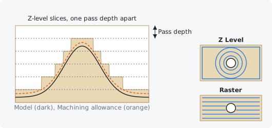
At each level, everything inside the Boundary is cleared except where the tool would cut into the model (plus the allowance) at that height. The last level is at the lowest point the tool needs to reach, never below the material bottom. The result is a staircase that follows the model, with steps no taller than the pass depth.
Pick a sturdy flat end mill (6 mm or 1/4" is common) and use its usual Pass depth and Stepover (from the tool's settings, or the overrides below). A smaller tool gets closer to fine detail but takes longer.
Machining allowance #
How much material roughing leaves over the model, measured straight up. The finishing toolpath removes it.
Leave enough that the roughing tool's steps never touch the final surface, but not so much that the finishing tool has to take a heavy cut: 0.3 to 1 mm is typical (the default is 0.5 mm). Use 0 only when there will be no finishing pass.
Strategy #
How each level is cleared. Z Level clears with offsets that follow the outline of the area at that height; Raster clears with parallel back-and-forth lines at the Raster angle.
Z Level leaves cleaner walls round the model and keeps the tool in steady contact; it is the usual choice. Raster can be quicker on large open areas and simpler shapes. Both cut in climb direction and finish each level with a pass round its edges.
Pass depth override #
The height between levels. 0 uses the Pass depth of the tool's settings.
Smaller steps leave less material for the finishing pass on steep slopes but take longer. A pass depth of about half the tool's diameter is a common starting point in wood.
Stepover override #
The distance between neighbouring passes within a level. 0 uses the Stepover of the tool's settings.
For roughing, 40 to 50% of the tool's diameter is typical.
3D Finishing #
3D finishing runs the tool over the relief's surface with a fine stepover, the tool's tip riding up and down on the model. It gives the final shape and surface.
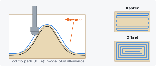
Each line is dropped onto the model: at every point the tool goes as low as it can without cutting into it. Between lines that are close together and inside the boundary, the tool carries on along the surface instead of lifting, which saves time.
Use a ball nose for finishing: its round tip blends the passes into a smooth surface. The smaller the tool and the stepover, the finer the detail and the smoother the result, and the longer it takes. Rough first with 3D Roughing unless the model is shallow enough for the finishing tool to cut it in one go.
Strategy #
The pattern of the passes. Raster runs parallel back-and-forth lines at the Raster angle; Offset runs rings that follow the Boundary inward, one stepover apart.
Raster is the usual choice and works for any shape; set the angle along the long direction of the model or along the wood grain. Offset suits round or framed models whose features follow the boundary.
Allowance #
Material left over the model, measured straight up. Normally 0, so the tool finishes on the model's surface.
Use a small allowance (for example 0.2 mm) for a semi-finishing pass with a larger tool, followed by a final pass at 0 with a small one.
Stepover override #
The distance between neighbouring passes. 0 uses the Stepover of the tool's settings.
With a ball nose, 8 to 15% of the diameter gives a smooth finish (0.5 mm for a 6 mm ball); up to 20% is fine for a rougher, faster finish. Halving the stepover doubles the time.
Boundary and raster angle #
These options work the same way on both 3D toolpaths.
Boundary #
The area the toolpath machines. Material boundary covers the whole material; Model boundary follows the outline where the model rises above its base; Selected vectors uses the closed vectors you selected.
The boundary limits the tool's centre, so with Material boundary the tool runs right out to the edges of the stock. Model boundary saves time when the model covers only part of the material. Selected vectors lets you machine one area of the model at a time, or a detail with a smaller tool; open vectors are skipped. If the model has no outline (it is flat), the material boundary is used.
Boundary offset #
Grows the boundary outward by this distance, or shrinks it inward when it is negative. The tool's centre stays inside the offset boundary.
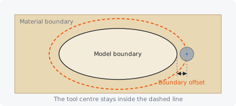
With Model boundary or Selected vectors, an offset of about the tool's radius lets the tool run fully off the edge of the shape, so the edge is cut cleanly. A negative offset with Material boundary keeps the tool inside the stock, for example clear of clamps.
Raster angle #
The direction of the raster lines, in degrees, when the strategy is Raster. 0° runs them along X, 90° along Y.
For finishing in wood, running along the grain usually gives the smoothest surface. Two finishing toolpaths at 0° and 90° remove most of the small ridges a single direction leaves.